-
1.What is the size, current and voltage rating of this connector?
The Male DVI Connector is a widely used connector in the audiovisual industry that allows for high-quality digital video and audio transmission. Here is a detailed introduction to the size, current rating, and voltage rating of the Male DVI Connector:
Size: The Male DVI Connector comes in different sizes, including DVI-A, DVI-D, and DVI-I. The DVI-A connector is the analog-only variant and has 17 pins arranged in three rows. The DVI-D connector is the digital-only variant and has 24 pins arranged in three rows. The DVI-I connector is the integrated variant and has all the pins required for both analog and digital signals.
Current Rating: The Male DVI Connector does not have a specific current rating since it primarily carries digital video and audio signals. However, the pins and contacts within the connector are designed to handle the low-level electrical currents required for transmitting these signals without any significant power loss or distortion.
Voltage Rating: The Male DVI Connector is typically used for transmitting digital video and audio signals, which operate at low voltages. The voltage rating of the connector is not specifically defined since it depends on the specific application and the devices connected. However, it is commonly used for transmitting signals in the range of 0.3 to 0.5 volts.
Compatibility: The Male DVI Connector is compatible with various devices, including computers, monitors, projectors, and televisions. It is commonly used for connecting digital displays to video sources and supports high-resolution video signals, making it popular in applications that require high-quality visuals, such as gaming, multimedia production, and professional presentations.
Signal Transmission: The Male DVI Connector supports the transmission of digital video signals, including DVI Single-Link and DVI Dual-Link formats. It can carry uncompressed video signals and supports various video resolutions, including Full HD (1080p), 2K, and 4K resolutions. Some variants of the Male DVI Connector also support the transmission of digital audio signals.
Quality and Reliability: The Male DVI Connector is known for its high-quality construction, which ensures reliable signal transmission and durability. It is designed to minimize signal loss and interference, resulting in clear and stable video and audio quality. The connectors are typically made of high-quality materials such as metal shells and gold-plated contacts, which provide excellent conductivity, corrosion resistance, and long-term reliability.
In conclusion, the Male DVI Connector comes in different sizes, including DVI-A, DVI-D, and DVI-I, and is primarily used for transmitting digital video and audio signals. It is compatible with various devices and supports high-resolution video signals. The connector is known for its high-quality construction, ensuring reliable signal transmission and durability.2. Are there different socket types to choose from?
Yes, there are different socket types available for the Male DVI Connector. The Male DVI Connector is designed to mate with its corresponding Female DVI Connector, creating a secure and reliable connection for digital video and audio transmission. Here are the different socket types available for the Male DVI Connector:
DVI-A Socket: The DVI-A socket is the analog-only variant of the Male DVI Connector. It consists of 17 pins arranged in three rows. The DVI-A socket is used for transmitting analog video signals and is commonly found in older devices that do not support digital video.
DVI-D Socket: The DVI-D socket is the digital-only variant of the Male DVI Connector. It consists of 24 pins arranged in three rows. The DVI-D socket is used for transmitting digital video signals and is commonly found in modern devices that support digital video. It provides a high-quality, noise-free digital video transmission.
DVI-I Socket: The DVI-I socket is the integrated variant of the Male DVI Connector. It consists of all the pins required for both analog and digital signals. The DVI-I socket can transmit both analog and digital video signals, making it compatible with a wide range of devices. It is commonly used in applications where both analog and digital video signals need to be supported.
Each socket type has a specific configuration of pins that ensures proper alignment and connection with the matching Female DVI Connector. It is important to select the correct socket type to ensure compatibility and optimal performance of the Male DVI Connector.
In addition to the different socket types, Male DVI Connectors are available in various sizes and form factors, such as standard size, mini, and micro. These different sizes and form factors are designed to accommodate different space constraints and device requirements.
In conclusion, the Male DVI Connector is available in different socket types, including DVI-A, DVI-D, and DVI-I. Each socket type is designed to accommodate specific types of video signals and is compatible with corresponding Female DVI Connectors. It is important to choose the correct socket type to ensure compatibility and optimal performance.3.Main purposes and application areas
The Male DVI Connector is a widely used connector in the audiovisual industry that allows for high-quality digital video and audio transmission. It plays a crucial role in connecting various devices, such as computers, monitors, projectors, and televisions, to display digital content. Here is a detailed introduction to the main purposes and application areas of the Male DVI Connector:
Main Purposes:
Digital Video Transmission: The primary purpose of the Male DVI Connector is to transmit digital video signals. It supports high-resolution video formats, including Full HD (1080p), 2K, and 4K resolutions. The connector ensures a stable and reliable transmission of uncompressed video signals, resulting in clear and vibrant visuals.
Digital Audio Transmission (Some Variants): In addition to video, certain variants of the Male DVI Connector also support the transmission of digital audio signals. This allows for a complete multimedia experience by transmitting both high-quality video and audio signals through a single connector.
High-Quality Signal Transmission: The Male DVI Connector is designed to minimize signal loss and interference, ensuring a high-quality transmission of video and audio signals. It provides excellent image clarity, color accuracy, and video playback without any distortion or degradation.
Application Areas:
Gaming: The Male DVI Connector is widely used in gaming setups to connect gaming consoles or computers to monitors or televisions. It supports high-resolution gaming and ensures a smooth and immersive gaming experience with minimal input lag.
Multimedia Production: The Male DVI Connector finds extensive use in multimedia production environments such as video editing studios and post-production facilities. It allows for the accurate display of high-resolution video content, ensuring precise color grading and accurate visual representation.
Professional Presentations: In professional settings such as conference rooms and boardrooms, the Male DVI Connector enables the connection of laptops or presentation systems to projectors or large displays. It ensures crisp and clear visuals, enhancing the effectiveness of presentations and meetings.
Digital Signage: The Male DVI Connector is commonly used in digital signage applications, where it facilitates the connection between media players and digital displays. It ensures the delivery of high-quality content, enabling dynamic and engaging visual communication in retail stores, airports, stadiums, and other public spaces.
Home Entertainment: The Male DVI Connector is utilized in home theater systems to connect DVD players, Blu-ray players, or media streaming devices to high-definition televisions or projectors. It allows for the transmission of high-quality video and audio signals, providing a cinematic experience in the comfort of one's home.
In conclusion, the Male DVI Connector serves as a reliable and versatile connector for digital video and audio transmission. Its main purposes include transmitting digital video signals, supporting digital audio transmission (certain variants), and ensuring high-quality signal transmission. It finds applications in gaming, multimedia production, professional presentations, digital signage, and home entertainment, enhancing the visual experience in various settings.4. How durable and reliable is it?
The Male DVI Connector is known for its durability and reliability, making it a popular choice in the audiovisual industry. Here is a detailed introduction to its durability and reliability:
Construction: The Male DVI Connector is typically made with high-quality materials such as metal shells and gold-plated contacts. These materials provide excellent conductivity, corrosion resistance, and long-term durability. The connectors are designed to withstand frequent plugging and unplugging without compromising their structural integrity.
Signal Transmission: The Male DVI Connector is designed to minimize signal loss and interference, ensuring a reliable transmission of digital video and audio signals. The pins and contacts within the connector are precisely engineered to maintain a stable connection, resulting in clear and stable video and audio quality. The connector's design ensures that there is no signal degradation or distortion during transmission.
Robust Design: The Male DVI Connector is designed to withstand the rigors of everyday use. It is built to be resistant to physical stresses, including bending, twisting, and accidental impacts. The connectors are often tested to meet industry standards for durability and reliability, ensuring that they can withstand the demands of professional settings.
Longevity: The Male DVI Connector is built to last. The high-quality materials used in its construction and the robust design ensure that it can withstand the test of time. The connectors are resistant to wear and tear, maintaining their performance even after prolonged use. This longevity makes the Male DVI Connector a cost-effective choice for individuals and businesses.
Industry Standards: The Male DVI Connector complies with industry standards for durability and reliability. It is often tested and certified by regulatory bodies to ensure that it meets the required performance standards. These certifications provide assurance that the connector will perform reliably under various conditions.
Customer Feedback: The Male DVI Connector has received positive feedback from users for its durability and reliability. Many customers have reported using the connector for extended periods without experiencing any issues. This feedback is a testament to the connector's quality and ability to deliver consistent performance.
In conclusion, the Male DVI Connector is known for its durability and reliability. Built with high-quality materials and a robust design, it ensures a stable and uninterrupted transmission of digital video and audio signals. The connector's longevity and compliance with industry standards make it a trusted choice for professionals and individuals seeking a reliable audiovisual connection.5. How does it work?
The Male DVI Connector is an essential component in connecting devices that require digital video and audio transmission. It works by establishing a secure and reliable connection between the Male DVI Connector and its corresponding Female DVI Connector. Here is a detailed explanation of how it works:
Connector Design: The Male DVI Connector is designed with a specific configuration of pins that correspond to the pins in the Female DVI Connector. These pins ensure proper alignment and connection between the two connectors. The connector is typically made of metal shells with gold-plated contacts, which provide excellent conductivity and corrosion resistance.
Digital Video Transmission: The Male DVI Connector is primarily used for transmitting digital video signals. It supports high-resolution video formats, including Full HD (1080p), 2K, and 4K resolutions. The digital video signals are transmitted through the pins in the connector, ensuring a stable and reliable transmission. This results in clear and vibrant visuals on the connected display device.
Signal Transmission: The pins and contacts within the Male DVI Connector are precisely engineered to maintain a stable connection and minimize signal loss and interference. The digital video signals are transmitted as binary data through the pins, ensuring accurate representation of the video content. The connector's design ensures that there is no signal degradation or distortion during transmission.
Single Link and Dual Link Variants: The Male DVI Connector comes in two variants: Single Link and Dual Link. The Single Link variant consists of 18 pins arranged in three rows, while the Dual Link variant consists of 24 pins arranged in three rows. The Dual Link variant supports higher resolutions and provides a higher bandwidth for transmitting digital video signals.
Audio Transmission (Some Variants): Certain variants of the Male DVI Connector also support the transmission of digital audio signals. These variants have additional pins dedicated to transmitting audio signals. This allows for a complete multimedia experience by transmitting both high-quality video and audio signals through a single connector.
Plug and Play: The Male DVI Connector is designed for easy plug-and-play functionality. It can be easily inserted into the corresponding Female DVI Connector without the need for additional tools or adjustments. Once connected, the Male DVI Connector establishes a secure and reliable connection, ensuring a seamless transmission of digital video and audio signals.
In conclusion, the Male DVI Connector works by establishing a secure and reliable connection with the Female DVI Connector. It transmits digital video signals through a specific configuration of pins and ensures a stable and accurate representation of the video content. Certain variants also support the transmission of digital audio signals. With its plug-and-play functionality, the Male DVI Connector provides a convenient solution for connecting devices that require digital video and audio transmission.6. How to install and use?
Installing and using the Male DVI Connector is a straightforward process. Here is a step-by-step guide on how to install and use the connector:
Identify the Male DVI Connector: The Male DVI Connector has pins that correspond to the Female DVI Connector. It is usually made of metal shells and has gold-plated contacts. Familiarize yourself with the connector's appearance and design before proceeding.
Check for Compatibility: Ensure that the devices you want to connect have Female DVI Connectors. The Male DVI Connector is designed to fit into the Female DVI Connector, so it is essential to verify compatibility.
Power Off Devices: Before connecting or disconnecting any cables, it is crucial to power off all devices involved. This ensures safety and prevents any potential damage to the equipment.
Align the Connectors: Take the Male DVI Connector and align it with the Female DVI Connector. The pins on the Male DVI Connector should correspond to the holes in the Female DVI Connector. Make sure the connectors are properly aligned before proceeding to the next step.
Insert the Connector: Gently insert the Male DVI Connector into the Female DVI Connector. Apply even pressure and avoid forcing the connector into the slot. The connectors should fit smoothly together. If there is any resistance, double-check the alignment and try again.
Secure the Connection: Once the connectors are fully inserted, secure the connection by tightening any screws or latches if present. This ensures a secure and stable connection between the devices.
Power On Devices: After the connection is secure, power on the devices. Allow them to boot up and establish a connection. Depending on the devices, you may need to select the appropriate input source or adjust display settings.
Test the Connection: To ensure that the connection is working correctly, check the display on the connected device. Verify that the video and audio, if supported, are being transmitted successfully. If there are any issues, double-check the connection and settings.
Adjust Display Settings: Depending on the devices and preferences, you may need to adjust the display settings. This includes resolution, aspect ratio, refresh rate, and color calibration. Consult the user manuals of the devices for guidance on adjusting the settings.
Disconnecting the Connector: When you need to disconnect the Male DVI Connector, make sure to power off the devices first. Then, gently remove the connector by pulling it straight out. Avoid twisting or bending the connector, as it may cause damage.
In conclusion, installing and using the Male DVI Connector involves aligning and connecting the corresponding Male and Female DVI Connectors. It is essential to ensure compatibility, power off devices before installation, and follow proper procedures for connecting and disconnecting the connector. By following these steps, you can easily install and use the Male DVI Connector to transmit digital video and, in some cases, audio signals between compatible devices.
-
1.What is the size, current and voltage rating of this connector?
The Solder Cup Power D-Sub Connector is a versatile and reliable connector commonly used in various electronic applications. This type of connector is known for its robust construction and ability to handle high power and signal transmission requirements. Here is a detailed introduction to the Solder Cup Power D-Sub Connector:
Size:
The Solder Cup Power D-Sub Connector is available in standard sizes ranging from 9 to 50 pins. The size of the connector is typically determined by the number of pins or contacts it contains. The dimensions of the connector are designed to fit standard D-Sub connector cutouts, making it compatible with a wide range of devices and equipment.
Current Rating:
The Solder Cup Power D-Sub Connector is capable of handling high current ratings, typically ranging from 5 to 40 Amperes per contact. This makes it suitable for applications that require the transmission of power and signals simultaneously. The connector's design ensures efficient power delivery while maintaining a stable electrical connection.
Voltage Rating:
The Solder Cup Power D-Sub Connector is designed to withstand high voltage levels, with voltage ratings typically ranging from 250 to 600 Volts. This allows the connector to be used in applications where high voltage requirements are essential, such as power distribution systems, industrial machinery, and communication equipment. The insulation properties of the connector help ensure safe and reliable operation even at high voltage levels.
Features:
The Solder Cup Power D-Sub Connector features solder cup contacts that provide a secure and stable connection between the connector and the wires or cables. The solder cups are designed to accommodate a wide range of wire gauges, allowing for flexibility in terms of wire size and compatibility. Additionally, the connector is equipped with metal shells for enhanced durability and protection against electromagnetic interference (EMI).
Applications:
The Solder Cup Power D-Sub Connector is commonly used in industrial automation, telecommunications, power distribution, instrumentation, and data communication applications. Its high current and voltage ratings make it ideal for applications that require the transmission of power signals over long distances. The connector is also suitable for harsh environments thanks to its robust construction and reliable performance.
In conclusion, the Solder Cup Power D-Sub Connector is a versatile and high-performance connector designed to meet the demanding requirements of power and signal transmission applications. With its high current and voltage ratings, durable construction, and compatibility with various wire gauges, this connector is a reliable choice for a wide range of electronic and industrial applications.2. Are there different socket types to choose from?
The Solder Cup Power D-Sub Connector is available in different socket types to accommodate various wiring configurations and preferences. Here is a detailed to the different socket types available for the Solder Cup Power D-Sub Connector:
Standard Solder Cups: This is the most common type of socket for the Solder Cup Power D-Sub Connector. It features solder cups that allow wires or cables to be soldered directly onto the connector. This type of socket provides a secure and reliable connection, making it suitable for a wide range of applications.
Insulated Solder Cups: In some applications, it may be necessary to insulate the solder cups to prevent electrical short circuits or to meet specific safety requirements. Insulated solder cups feature a protective insulating material that surrounds the solder cups, providing electrical insulation between contacts. This type of socket ensures proper isolation and prevents accidental contact between adjacent pins.
Screw Terminal Sockets: Screw terminal sockets provide an alternative method for connecting wires or cables to the Solder Cup Power D-Sub Connector. Instead of soldering, wires or cables are secured using screws that clamp onto the stripped ends of the wires. This type of socket is popular for applications where frequent wire changes or connections are required.
IDC (Insulation Displacement Connector) Sockets: IDC sockets offer a convenient and time-saving solution for wire termination. They feature small metal contacts that pierce through the wire insulation, making a reliable electrical connection. IDC sockets eliminate the need for soldering or stripping wire ends, which can save time and reduce the risk of human error during installation.
High-Density Sockets: High-density sockets are designed to accommodate a larger number of pins or contacts in a smaller footprint. These sockets have a higher pin density, allowing for more connections in a limited space. High-density Solder Cup Power D-Sub Connectors are commonly used in applications where space is a premium, such as in aerospace, military, and telecommunications industries.
It's important to note that the availability of different socket types may vary depending on the manufacturer and specific product line. When selecting the Solder Cup Power D-Sub Connector, it is recommended to consult the manufacturer's catalog or datasheet to determine the available socket types and choose the one that best suits your application requirements.
In conclusion, the Solder Cup Power D-Sub Connector offers a range of socket types to accommodate different wiring configurations and installation preferences. Whether you prefer standard solder cups, insulated solder cups, screw terminals, IDC sockets, or high-density sockets, there is a suitable option available to meet your specific needs.3.Main purposes and application areas
The Solder Cup Power D-Sub Connector is a versatile and widely used connector in various industries and applications. It is designed to provide a secure and reliable connection for power and signal transmission. Here is a detailed introduction to the main purposes and application areas of the Solder Cup Power D-Sub Connector:
Main Purposes:
Power Transmission: One of the main purposes of the Solder Cup Power D-Sub Connector is to transmit power efficiently and reliably. It is capable of handling high current ratings, typically ranging from 5 to 40 Amperes per contact. This makes it suitable for applications that require the transmission of power, such as power distribution systems, industrial machinery, and power supplies.
Signal Transmission: In addition to power transmission, the Solder Cup Power D-Sub Connector is also used for signal transmission. It provides a stable and secure connection for transmitting signals between devices and components. This makes it ideal for applications that require the transmission of control signals, data signals, and communication signals.
Industrial Automation: The Solder Cup Power D-Sub Connector is widely used in industrial automation applications. It is commonly found in PLCs (Programmable Logic Controllers), motor drives, sensors, and other industrial control systems. Its robust construction, high current and voltage ratings, and reliable performance make it suitable for demanding industrial applications.
Telecommunications: The Solder Cup Power D-Sub Connector is utilized in telecommunications equipment and systems. It is commonly found in networking devices, communication modules, and telecom infrastructure. The connector's ability to handle high current and voltage, coupled with its secure and stable connection, makes it an ideal choice for transmitting signals in telecommunication networks.
Automotive and Transportation: The Solder Cup Power D-Sub Connector is also used in the automotive and transportation industry. It is utilized in various applications such as vehicle wiring systems, engine control units, and electronic control modules. The connector's ability to handle high current and voltage, along with its durable construction, makes it suitable for the demanding environment of automotive and transportation applications.
Aerospace and Defense: The Solder Cup Power D-Sub Connector finds applications in the aerospace and defense sectors. It is commonly used in avionics systems, military equipment, and communication systems. The connector's high reliability, robustness, and ability to handle high current and voltage make it suitable for the stringent requirements of aerospace and defense applications.
In conclusion, the Solder Cup Power D-Sub Connector serves a wide range of purposes and finds applications in various industries. Its ability to handle high current and voltage, along with its reliable performance, makes it a popular choice for power and signal transmission in industrial automation, telecommunications, automotive, aerospace, and defense applications.4. How durable and reliable is it?
The Solder Cup Power D-Sub Connector is known for its durability and reliability, making it a popular choice for a wide range of applications in various industries. Here is an in-depth introduction to the durability and reliability of the Solder Cup Power D-Sub Connector:
Durability:
The Solder Cup Power D-Sub Connector is constructed using high-quality materials such as metal shells, insulating materials, and solder cups that are designed to withstand mechanical stress, environmental factors, and repetitive use. The metal shells provide robust protection to the internal components of the connector, ensuring its durability in harsh conditions.
The solder cups of the connector are designed to securely hold the wires or cables in place, even under vibrations or movements. This ensures a stable connection that is resistant to loosening or breakage over time. Additionally, the connector's overall design and construction are engineered to meet industry standards for durability and longevity.
Reliability:
The Solder Cup Power D-Sub Connector is widely recognized for its high reliability in providing consistent and uninterrupted power and signal transmission. The connector's solder cups create a strong and reliable connection between the wires and contacts, minimizing the risk of signal loss or disruptions.
Moreover, the Solder Cup Power D-Sub Connector undergoes rigorous testing and quality assurance processes during manufacturing to ensure that it meets performance standards and specifications. This helps to guarantee its reliability in diverse applications where stable electrical connections are essential.
The connector's ability to handle high current and voltage levels without compromising its performance further enhances its reliability in demanding environments. Whether used in industrial automation, telecommunications, automotive, or aerospace applications, the Solder Cup Power D-Sub Connector is trusted for its consistent performance and reliability.
In conclusion, the Solder Cup Power D-Sub Connector is renowned for its durability and reliability in providing secure and stable connections for power and signal transmission. Its robust construction, high-quality materials, and stringent testing procedures make it a dependable choice for applications that require long-lasting and reliable electrical connections.5. How does it work?
The Solder Cup Power D-Sub Connector is a versatile and widely used connector that provides a reliable and secure connection for power and signal transmission. Here is a detailed explanation of how it works:
Connector Structure: The Solder Cup Power D-Sub Connector consists of a metal shell, contacts, insulating materials, and solder cups. The metal shell acts as a protective housing for the internal components and provides mechanical strength and durability. The insulating materials, typically made of high-quality plastics, ensure electrical insulation and prevent short circuits between contacts. The solder cups are designed to hold the stripped ends of wires or cables securely. This allows for a strong and reliable connection.
Soldering Process: The solder cups play a crucial role in the functioning of the connector. To create a connection, the wires or cables are stripped of their insulation, and the exposed conductive cores are inserted into the solder cups. The wires are then soldered to the cups using a soldering iron or a specialized soldering machine. The solder forms a permanent bond between the wires and the cups, creating a secure electrical connection.
Contact Design: The Solder Cup Power D-Sub Connector typically features a range of contacts, including power contacts, signal contacts, and ground contacts. These contacts are strategically positioned within the connector to ensure proper alignment and mating with the corresponding contacts in the mating connector. The contacts are made of high-quality materials, such as copper or gold-plated copper, to provide excellent conductivity and minimize signal loss.
Mating and Locking: The Solder Cup Power D-Sub Connector is designed to mate with a compatible connector, which may be another Solder Cup Power D-Sub Connector or a different type of D-Sub Connector. The mating process involves aligning the connectors and applying force to connect them. Once connected, the connectors are secured using locking mechanisms, such as screws or latches, to prevent accidental disconnection.
Power and Signal Transmission: The Solder Cup Power D-Sub Connector is capable of transmitting both power and signals. The power contacts can handle high current and voltage levels, making them suitable for power transmission applications. The signal contacts are designed to provide a reliable connection for transmitting control signals, data signals, and communication signals. The connector's design ensures minimal signal loss and interference, resulting in a stable and high-quality transmission.
In conclusion, the Solder Cup Power D-Sub Connector works by securely connecting wires or cables to the solder cups, creating a reliable electrical connection. Its robust structure, soldering process, contact design, and mating capabilities make it a versatile and efficient solution for power and signal transmission in various industries and applications.6. How to install and use?
Installing and using a Solder Cup Power D-Sub Connector is a straightforward process that involves a few key steps to ensure a secure and reliable connection for power and signal transmission. Here is a detailed guide on how to install and use a Solder Cup Power D-Sub Connector:
Preparation: Before installing the Solder Cup Power D-Sub Connector, gather all the necessary tools and materials, including the connector itself, wires or cables to be connected, a soldering iron, solder, wire strippers, and any other tools required for the job.
Stripping Wires: Begin by stripping the insulation from the ends of the wires or cables that will be connected to the Solder Cup Power D-Sub Connector. Use wire strippers to carefully remove the insulation, exposing the conductive cores of the wires.
Soldering: Insert the stripped ends of the wires into the solder cups of the connector. Apply heat from a soldering iron to the solder cups and wires while feeding solder into the joint. Ensure that the solder forms a secure bond between the wires and the cups. Be careful not to overheat the connector or apply too much solder, as this can lead to poor connections.
Securing the Connection: Once the wires are soldered to the cups, ensure that the connection is secure and there are no loose wires. Use a multimeter to check for continuity and verify that the connections are properly made.
Mating the Connectors: To use the Solder Cup Power D-Sub Connector, mate it with a compatible connector by aligning the pins or contacts and applying gentle pressure to connect them. Use any locking mechanisms, such as screws or latches, to secure the connection and prevent accidental disconnection.
Testing: After the connectors are mated, test the connection to ensure proper power and signal transmission. Verify that there is continuity between the connected devices and that signals are being transmitted accurately.
Maintenance: Regularly inspect the Solder Cup Power D-Sub Connector for any signs of wear or damage. Clean the connector periodically to remove any dust or debris that may affect its performance. Ensure that the solder joints are intact and re-solder any connections that may have come loose.
In conclusion, installing and using a Solder Cup Power D-Sub Connector involves stripping, soldering, securing, mating, testing, and maintaining the connector to ensure reliable power and signal transmission. By following these steps carefully and ensuring proper installation, you can create a secure and stable connection for your electrical applications.
-
1.What is the size, current and voltage rating of this connector?
The Floating Board To Board Connector is a versatile and widely used component in the electronics industry. It is designed to establish connections between circuit boards, allowing for the transmission of signals and power between them. Here is a comprehensive introduction to the Floating Board To Board Connector, including its size, current rating, and voltage rating.
Size: The Floating Board To Board Connector comes in various sizes to accommodate different application requirements. It is available in different pitch sizes, typically ranging from 0.5mm to 2.54mm. The pitch size refers to the distance between adjacent pins or contacts on the connector. The connector's overall dimensions may vary depending on the specific model and configuration.
Current Rating: The Floating Board To Board Connector is designed to handle different levels of current, depending on the specific model and configuration. The current rating of the connector is determined by factors such as the size and material of the contact pins, the contact resistance, and the temperature rise. Generally, the current rating can range from a few milliamps to several amps, allowing for a wide range of applications.
Voltage Rating: The Floating Board To Board Connector is designed to withstand specific levels of voltage without insulation breakdown or arcing. The voltage rating of the connector is determined by factors such as the dielectric strength of the materials used, the spacing between contacts, and the design of the insulation. The voltage rating can vary depending on the specific model and configuration, ranging from a few volts to several hundred volts.
It is important to note that the size, current rating, and voltage rating of the Floating Board To Board Connector may vary depending on the manufacturer and specific product series. It is essential to consult the product datasheet or contact the manufacturer for detailed specifications and ratings for a specific connector model.
In conclusion, the Floating Board To Board Connector is a versatile component used for establishing connections between circuit boards. Its size, current rating, and voltage rating may vary depending on the specific model and configuration. The connector's specifications determine its compatibility with different applications, and it is crucial to consider these factors when selecting and using the Floating Board To Board Connector in electronic designs.2. Are there different socket types to choose from?
Floating Board To Board Connectors are available in a variety of socket types to cater to different application requirements and design preferences. These socket types offer unique features and advantages, allowing designers to select the most suitable option for their specific needs. Here is a comprehensive overview of the different socket types available for Floating Board To Board Connectors:
Standard Socket: The standard socket type is the most common option for Floating Board To Board Connectors. It features a simple design with straight pins or contacts that provide a secure and reliable connection between circuit boards. Standard sockets are available in various pitch sizes to accommodate different spacing requirements between boards.
SMT Socket: Surface Mount Technology (SMT) sockets are designed for easy and efficient surface mounting on the circuit board. These sockets have solder pads instead of through-hole pins, allowing for automated assembly processes and saving space on the board. SMT sockets provide a low-profile solution for compact electronic designs.
Right-Angle Socket: Right-angle sockets are designed to create connections between circuit boards at a right angle. This configuration is useful when space constraints or specific board orientations require a perpendicular mating arrangement. Right-angle sockets ensure a secure connection while optimizing the use of available board space.
Stacked Socket: Stacked sockets feature multiple rows of contacts stacked on top of each other. This design allows for higher-density connections between boards, enabling designers to maximize the number of connections in a limited space. Stacked sockets are ideal for applications that require a high number of signal paths or data lines.
Floating Socket: Floating sockets provide a degree of freedom in the lateral movement of the connected boards. This flexibility compensates for any misalignment or thermal expansion between the boards, ensuring a reliable and stable connection. Floating sockets are suitable for applications where board alignment may vary due to mechanical stress or temperature fluctuations.
High-Speed Socket: High-speed sockets are designed to support high-frequency signal transmission between boards. These sockets feature optimized signal integrity characteristics, such as controlled impedance and reduced crosstalk, to maintain signal integrity in high-speed data transfers. High-speed sockets are ideal for applications that require reliable data communication at high data rates.
In conclusion, Floating Board To Board Connectors offer a range of socket types to suit different design requirements, including standard, SMT, right-angle, stacked, floating, and high-speed sockets. Designers can choose the appropriate socket type based on factors such as space constraints, alignment needs, signal integrity requirements, and ease of assembly. Selecting the right socket type is essential to ensure a successful and efficient board-to-board connection in electronic designs.3.Main purposes and application areas
Floating Board To Board Connectors are widely used in various industries and applications where the establishment of reliable and secure connections between circuit boards is crucial. Here is a comprehensive overview of the main purposes and application areas of Floating Board To Board Connectors:
Consumer Electronics: Floating Board To Board Connectors are extensively used in consumer electronics devices such as smartphones, tablets, laptops, and gaming consoles. These connectors enable the interconnection of different circuit boards within these devices, facilitating the transmission of signals and power.
Automotive: Automotive applications require robust and reliable connectors to ensure the proper functioning of various electronic components. Floating Board To Board Connectors are utilized in automotive systems for applications such as infotainment systems, dashboard displays, advanced driver-assistance systems (ADAS), and engine control units (ECU).
Industrial Equipment: Floating Board To Board Connectors find application in industrial equipment and machinery, where they enable the connection of control boards, sensors, and actuators. These connectors are commonly used in robotics, automation systems, machine vision systems, and control panels.
Telecommunications: Floating Board To Board Connectors play a vital role in the telecommunications industry, providing connectivity solutions for network equipment, switches, routers, and base stations. These connectors ensure reliable data transmission and signal integrity in high-speed and high-frequency telecommunications applications.
Medical Devices: Medical devices require connectors that can withstand harsh environments and ensure secure connections. Floating Board To Board Connectors are used in medical equipment such as patient monitoring systems, imaging equipment, diagnostic devices, and surgical instruments. They provide the necessary connectivity for the proper functioning of these critical devices.
Aerospace and Defense: Floating Board To Board Connectors are utilized in aerospace and defense applications where high reliability and ruggedness are required. These connectors are used in avionics systems, satellite communication systems, military vehicles, and radar systems.
LED Lighting: Floating Board To Board Connectors are employed in LED lighting applications, connecting LED driver boards to LED modules or strips. These connectors enable the transmission of power and control signals, ensuring efficient and reliable operation of LED lighting systems.
Renewable Energy: Floating Board To Board Connectors are used in renewable energy systems such as solar power and wind power generation. These connectors facilitate the interconnection of control boards and power electronics, enabling efficient energy conversion and management.
In conclusion, Floating Board To Board Connectors have a wide range of applications in various industries, including consumer electronics, automotive, industrial equipment, telecommunications, medical devices, aerospace and defense, LED lighting, and renewable energy. These connectors play a crucial role in establishing reliable connections between circuit boards, ensuring the proper functioning of electronic systems and devices.4. How durable and reliable is it?
Floating Board To Board Connectors are known for their durability and reliability, making them a popular choice for various electronic applications. Here is a comprehensive description of the durability and reliability features of Floating Board To Board Connectors:
Materials: Floating Board To Board Connectors are typically manufactured using high-quality materials such as stainless steel, phosphor bronze, and high-temperature resistant plastics. These materials offer excellent durability, ensuring the connectors can withstand mechanical stress, temperature variations, and environmental factors.
Contact Design: Floating Board To Board Connectors feature well-designed contact points that provide a secure and reliable connection. The contact pins or pads are often plated with materials such as gold or palladium to enhance their conductivity and corrosion resistance. This ensures a long-lasting and reliable connection between the boards.
Shock and Vibration Resistance: Floating Board To Board Connectors are designed to withstand shock and vibration, which are common occurrences in many applications. The connectors often have features such as locking mechanisms or additional support structures to prevent accidental disconnection due to external forces.
Environmental Resistance: Floating Board To Board Connectors are engineered to resist various environmental factors such as moisture, dust, and chemicals. They may have sealing features or use materials that provide protection against these elements, ensuring reliable performance even in challenging environments.
Lifecycle and Durability Testing: Manufacturers subject Floating Board To Board Connectors to extensive lifecycle and durability testing to ensure their performance under real-world conditions. These tests simulate repeated mating and unmating cycles, temperature variations, and exposure to different environmental factors. Connectors that pass these tests are considered highly durable and reliable.
Quality Control: Floating Board To Board Connectors undergo strict quality control measures during their manufacturing process. Manufacturers often implement stringent quality assurance practices such as ISO certifications and in-house testing procedures to ensure the connectors meet industry standards and customer expectations.
Industry Compliance: Floating Board To Board Connectors are designed and manufactured to comply with industry standards and regulations. Compliance with standards such as UL, RoHS, and REACH ensures that the connectors are safe, reliable, and environmentally friendly.
In conclusion, Floating Board To Board Connectors are known for their durability and reliability. They are designed using high-quality materials, feature well-engineered contact points, and undergo rigorous testing and quality control measures. These connectors can withstand mechanical stress, temperature variations, shock, vibration, and environmental factors, providing a long-lasting and secure connection between circuit boards.5. How does it work?
Floating Board To Board Connectors work by providing a secure and reliable electrical connection between two circuit boards. These connectors consist of two main components: the socket, which is attached to one circuit board, and the header, which is attached to the other circuit board.
The socket and header are designed to fit together, creating a mating interface for the connection. The socket typically has a series of pins or contacts, while the header has corresponding slots or receptacles. When the socket and header are properly aligned, the pins or contacts on the socket make contact with the slots or receptacles on the header, creating an electrical pathway between the two circuit boards.
The pins or contacts on the socket are usually spring-loaded, allowing for a certain degree of movement or float. This float enables the connectors to compensate for any misalignment or thermal expansion between the circuit boards. It helps maintain a reliable and stable connection, even in dynamic or changing conditions.
To establish the connection, the circuit boards are aligned and brought together, allowing the pins or contacts on the socket to enter the slots or receptacles on the header. Once the connection is made, the pins or contacts exert a force on the slots or receptacles, ensuring a secure and stable electrical connection.
Floating Board To Board Connectors can be used in various applications, such as consumer electronics, automotive systems, industrial equipment, telecommunications, medical devices, aerospace and defense, LED lighting, and renewable energy. The connectors are designed to accommodate different spacing requirements, orientations, and signal integrity needs, depending on the specific application.
In summary, Floating Board To Board Connectors work by providing a reliable and secure electrical connection between two circuit boards. They use spring-loaded pins or contacts to establish the connection and allow for a certain degree of movement or float to compensate for misalignment or thermal expansion. These connectors play a crucial role in enabling the seamless integration and functioning of electronic devices and systems.6. How to install and use?
Installing and using Floating Board To Board Connectors is a straightforward process that requires careful attention to ensure a proper and secure connection. Here are the steps to install and use Floating Board To Board Connectors:
Preparation: Before installing the connectors, ensure that the circuit boards are clean and free from any debris or contaminants. This will help to establish a reliable and stable connection.
Connector Selection: Choose the appropriate Floating Board To Board Connector for your specific application. Consider factors such as pitch, orientation, and the number of contacts required.
Aligning the Connector: Place the socket connector on one circuit board and the header connector on the other circuit board. Make sure the connectors are properly aligned, ensuring that the pins or contacts on the socket line up with the slots or receptacles on the header.
Connection: Gently press the two circuit boards together, allowing the pins or contacts on the socket to enter the slots or receptacles on the header. Apply even pressure to ensure a secure and reliable connection. If necessary, use a magnifying glass or microscope to verify that all pins or contacts are properly aligned and inserted.
Locking Mechanism: Some Floating Board To Board Connectors feature locking mechanisms to provide additional stability and prevent accidental disconnection. If your connector has a locking feature, engage it according to the manufacturer's instructions.
Testing: Once the connection is established, test the electrical continuity and signal integrity between the circuit boards using appropriate testing equipment. This will help to ensure that the connection is reliable and that there are no issues with signal transmission.
Regular Inspection: It is important to regularly inspect the connectors for any signs of damage or wear. Check for loose pins or contacts, bent or broken parts, or any other abnormalities. If any issues are found, replace the connectors to maintain a reliable connection.
Removal: When removing Floating Board To Board Connectors, use caution to avoid damaging the circuit boards or the connectors themselves. Gently separate the two circuit boards, ensuring that no excessive force is applied.
In conclusion, installing and using Floating Board To Board Connectors involves aligning the connectors, pressing the circuit boards together, and ensuring a secure connection. Regular inspection and testing are essential to maintain the reliability of the connection. By following these steps, you can successfully install and use Floating Board To Board Connectors in various electronic applications.
-
1.What is the size, current and voltage rating of this connector?
2.0mm Hard Metric Connectors are a type of board-to-board connector that is widely used in various industries for their small size, high-density, and reliable performance. These connectors are designed to provide a compact and efficient solution for connecting circuit boards in applications where space is limited.
In terms of size, 2.0mm Hard Metric Connectors have a pitch of 2.0mm, which refers to the distance between the centerlines of adjacent pins. The compact size of these connectors allows for high-density packaging, making them ideal for applications that require a large number of connections in a limited space.
The current and voltage rating of 2.0mm Hard Metric Connectors can vary depending on the specific design and manufacturer. However, these connectors are typically rated for moderate to high current and voltage levels. The current rating can range from a few amps to several tens of amps, depending on the size and design of the connector. The voltage rating can range from a few volts to several hundred volts, depending on the insulation properties and design of the connector.
It is important to note that the current and voltage ratings of a connector are specified by the manufacturer and should be carefully considered when selecting a connector for a particular application. It is crucial to choose a connector with a current and voltage rating that is appropriate for the specific requirements of the application to ensure safe and reliable operation.
In addition to size, current, and voltage ratings, 2.0mm Hard Metric Connectors may also have other features and specifications that enhance their performance and reliability. These may include gold-plated contacts for improved conductivity and corrosion resistance, shielded designs to minimize electromagnetic interference, and various locking mechanisms to ensure a secure and vibration-resistant connection.
Overall, 2.0mm Hard Metric Connectors offer a compact and reliable solution for board-to-board connections in applications where space is limited. Their small size, high-density packaging, and moderate to high current and voltage ratings make them suitable for a wide range of industries, including telecommunications, industrial automation, computer systems, and consumer electronics. By carefully considering the size, current, and voltage rating, as well as other features, engineers can choose the appropriate 2.0mm Hard Metric Connector for their specific application, ensuring a reliable and efficient connection between circuit boards.2. Are there different socket types to choose from?
Yes, there are different socket types available for 2.0mm Hard Metric Connectors. These socket types offer flexibility and versatility in board-to-board connections, allowing engineers to choose the most suitable option for their specific application requirements.
One common type of socket used in 2.0mm Hard Metric Connectors is the straight socket. This type of socket has pins that are oriented perpendicular to the circuit board, providing a direct connection between two boards in a straight line. Straight sockets are ideal for applications where a simple and straightforward board-to-board connection is needed.
Another type of socket is the right-angle socket. This type of socket has pins that are oriented at a right angle to the circuit board. Right-angle sockets are often used when boards need to be connected at a 90-degree angle or when space constraints require a compact and space-saving design. This allows for more flexibility in board placement and routing.
Furthermore, there are also surface mount sockets available for 2.0mm Hard Metric Connectors. Surface mount sockets are designed to be mounted directly on the surface of the circuit board, eliminating the need for through-hole soldering. They provide a more convenient and efficient solution for high-density board-to-board connections, as they can be easily placed and soldered using automated assembly processes.
Additionally, hybrid sockets are available, which combine the features of both straight and right-angle sockets. Hybrid sockets provide greater flexibility in board placement and orientation, allowing for connections at different angles and orientations within the same connector system.
It is important to consider the specific application requirements, including board layout and space constraints, when selecting the appropriate socket type for 2.0mm Hard Metric Connectors. Engineers should also consider factors such as the number of pins required, mating force, and the overall durability and reliability of the connector system.
In conclusion, 2.0mm Hard Metric Connectors offer a range of socket types to choose from, including straight sockets, right-angle sockets, surface mount sockets, and hybrid sockets. These socket types provide flexibility and versatility in board-to-board connections, allowing engineers to select the most suitable option for their specific application needs.3.Main purposes and application areas
2.0mm Hard Metric Connectors are widely used in various industries and applications due to their versatility and reliability. These connectors offer a reliable and efficient solution for board-to-board and wire-to-board connections.
One of the main purposes of 2.0mm Hard Metric Connectors is to provide a connection interface between printed circuit boards (PCBs). They allow for the secure and stable transfer of signals, power, and data between different boards in electronic devices. These connectors are commonly used in applications such as telecommunications equipment, computer systems, industrial automation, medical devices, and automotive electronics.
In the telecommunications industry, 2.0mm Hard Metric Connectors are used in networking and communication equipment, including routers, switches, and servers. These connectors provide high-speed transmission of signals and data, ensuring reliable and efficient communication.
In computer systems, 2.0mm Hard Metric Connectors are utilized in motherboards, expansion cards, and peripheral devices. They enable the connection between different components, such as processors, memory modules, graphics cards, and storage devices. These connectors ensure the smooth operation and data transfer within the computer system.
Industrial automation is another key area where 2.0mm Hard Metric Connectors find extensive use. They are employed in control systems, PLCs (Programmable Logic Controllers), and industrial machinery. These connectors provide a reliable and secure connection between various sensors, actuators, and control modules, ensuring the efficient operation of the automated systems.
In the medical field, 2.0mm Hard Metric Connectors are utilized in medical devices and equipment. They are commonly found in patient monitoring systems, diagnostic equipment, and medical imaging devices. These connectors enable the transfer of signals and data, allowing for accurate monitoring and diagnosis of patients.
Automotive electronics also rely on 2.0mm Hard Metric Connectors for their electrical and electronic systems. These connectors are used in applications such as infotainment systems, engine control units, lighting systems, and advanced driver-assistance systems (ADAS). They provide a reliable and robust connection, ensuring the safe and efficient operation of the vehicle's electronic systems.
Overall, 2.0mm Hard Metric Connectors play a crucial role in various industries and applications. With their durability, reliability, and versatility, these connectors provide a reliable and efficient solution for board-to-board and wire-to-board connections, enabling the seamless transfer of signals, power, and data in electronic devices and systems.4. How durable and reliable is it?
2.0mm Hard Metric Connectors are highly regarded for their durability and reliability. These connectors are designed to withstand demanding operating conditions and provide a long-lasting and stable connection between circuit boards.
The durability of 2.0mm Hard Metric Connectors can be attributed to a combination of factors. Firstly, they are constructed using high-quality materials such as high-temperature thermoplastics and metal alloys. These materials offer excellent mechanical strength and resistance to wear and tear, ensuring that the connectors can withstand the rigors of daily use. Additionally, the pins and contacts of these connectors are often gold-plated, enhancing their durability by providing corrosion resistance and ensuring reliable electrical conductivity.
Moreover, 2.0mm Hard Metric Connectors are specifically engineered to withstand high levels of vibration and shock. They feature robust locking mechanisms such as latches or screws that keep the connectors securely in place, preventing accidental disconnections. This ensures a stable and reliable connection even in demanding environments where vibrations and shocks are common, such as in automotive or industrial applications.
In addition to their physical durability, 2.0mm Hard Metric Connectors are designed to provide reliable electrical performance. The contact design and materials used in these connectors minimize contact resistance, ensuring a low insertion force and reliable electrical connection. The connectors are often rated for high current and voltage levels, allowing them to handle demanding power requirements.
To ensure the reliability of 2.0mm Hard Metric Connectors, they undergo rigorous testing and quality control processes during manufacturing. These connectors are tested for factors such as mechanical strength, electrical performance, and temperature resistance. Compliance with industry standards and certifications further ensures their reliability.
It is important to note that the overall durability and reliability of 2.0mm Hard Metric Connectors can also depend on factors such as proper installation, maintenance, and the quality of the mating connectors. Following manufacturer guidelines and using compatible connectors will help ensure optimal performance and longevity.
In summary, 2.0mm Hard Metric Connectors are highly durable and reliable. Their robust construction, secure locking mechanisms, and high-quality materials contribute to their ability to withstand harsh environments and provide a stable and long-lasting connection. These connectors are trusted in various industries where reliability and durability are critical, such as telecommunications, industrial automation, and automotive applications.
5. How does it work?
2.0mm Hard Metric Connectors are designed to provide a reliable and efficient connection between circuit boards. They consist of male and female connector components that are specifically designed to interlock and create a secure electrical connection.
The working principle of 2.0mm Hard Metric Connectors is relatively straightforward. The male connector, also known as the pin header, is mounted onto one circuit board, while the female connector, also known as the receptacle, is mounted on the other circuit board. The male pins of the pin header are aligned with the corresponding female sockets of the receptacle.
To establish a connection, the two boards are brought together, aligning the male and female connectors. Once aligned, the male pins are inserted into the female sockets, creating a complete electrical connection. The pins and sockets are designed to have a tight fit, ensuring a secure and stable connection.
The pins of the male connector are typically made of conductive materials such as copper or brass, while the sockets of the female connector are made of a conductive material such as phosphor bronze. In some cases, the pins and sockets may be gold-plated to enhance conductivity and prevent corrosion.
2.0mm Hard Metric Connectors often feature a locking mechanism to ensure that the connection remains secure. This can be in the form of a latch, screw, or other locking mechanism. Once the connectors are fully inserted and locked, they will remain securely connected until intentionally disconnected.
These connectors are designed to handle high-speed data transmission, high power, and high-frequency signals. They provide a reliable and stable connection, minimizing signal loss and interference.
The modular design of 2.0mm Hard Metric Connectors allows for easy installation and removal, making them suitable for applications where frequent board-to-board connections are required. They are also designed to withstand various environmental conditions, such as temperature fluctuations, vibrations, and shocks, ensuring reliable performance in demanding applications.
In summary, 2.0mm Hard Metric Connectors work by interlocking male and female connector components to establish a secure and stable electrical connection between circuit boards. Their modular design, durability, and reliability make them a popular choice for a wide range of applications in industries such as telecommunications, industrial automation, and automotive electronics.6. How to install and use?
Installing and using 2.0mm Hard Metric Connectors is a relatively straightforward process. Here is a step-by-step guide on how to install and use these connectors:
Prepare the circuit boards: Ensure that the circuit boards you intend to connect are clean and free from any dust, debris, or contaminants. This will help ensure a reliable and secure connection.
Position the male and female connectors: Identify the male and female connectors on the respective circuit boards. The male connector, also known as the pin header, is usually mounted on one circuit board, while the female connector, known as the receptacle, is mounted on the other circuit board.
Align the connectors: Carefully align the male and female connectors so that the pins of the male connector are in line with the corresponding sockets of the female connector. Take caution to align them properly to avoid any damage to the pins or sockets.
Insert the pins into the sockets: Once the connectors are aligned, gently insert the pins of the male connector into the sockets of the female connector. Apply even pressure to ensure a smooth insertion. Make sure that the pins are fully inserted into the sockets for a secure connection.
Lock the connectors: If your 2.0mm Hard Metric Connectors have a locking mechanism, such as a latch or a screw, activate it to secure the connection. This will prevent any accidental disconnections caused by vibrations or movement.
Test the connection: Once the connectors are installed and locked, it is essential to test the connection to ensure it is secure and functional. Use appropriate testing equipment or procedures to verify that the signals, power, or data are being transmitted accurately between the connected circuit boards.
Proper handling and maintenance: To ensure the optimal performance and longevity of the connectors, handle them with care and avoid applying excessive force or pressure. Regularly inspect the connectors for any signs of damage or wear and clean them if necessary. Follow the manufacturer's guidelines for proper maintenance and handling.
Remember that proper installation and usage of 2.0mm Hard Metric Connectors are crucial to maintaining a reliable and secure connection. Following the steps outlined above and adhering to manufacturer guidelines will help ensure the connectors' optimal performance and longevity.
In summary, installing and using 2.0mm Hard Metric Connectors involves aligning the male and female connectors, inserting the pins into the sockets, locking the connectors if applicable, testing the connection, and practicing proper handling and maintenance. These connectors provide a reliable and efficient solution for board-to-board and wire-to-board connections in various industries and applications.
-
The battery connector is one of the key components in the battery system and is used to connect the battery to the circuit. With the continuous progress and development of science and technology, the technology of battery connectors is also constantly updated and improved. Here are a few key trends on battery connector technology:
1. Miniaturization: In order to improve the integration and compactness of the battery system, the battery connector is also gradually developing in the direction of miniaturization. By reducing the size and weight of the connector, you can reduce the space footprint inside the battery pack and reduce costs.
2. New battery interface: With the rapid development of electric vehicles, renewable energy and other fields, the requirements for battery performance are getting higher and higher. Therefore, new battery interface technologies are being researched and developed, such as nanomaterial coatings, conductive polymers, etc., to improve the conductivity and durability of batteries.
3. Low contact impedance: In the battery system, the contact resistance is an important parameter, which directly affects the energy conversion efficiency of the battery. To reduce contact resistance, researchers are exploring the use of novel materials to make thinner, softer connector contacts, as well as more efficient circuit designs to reduce current loss.
4. High connection reliability: Because battery connectors need to withstand extreme environmental conditions such as high temperature, high pressure and high energy density, high reliability is very important. For this reason, many manufacturers are developing connector materials and technologies with characteristics such as oxidation resistance, corrosion resistance and wear resistance to ensure their long-term stable operation.
In short, the future development trend of battery connectors will be more miniaturized, with better battery interfaces, low contact impedance and high connection reliability products. These technologies will help improve the efficiency and performance of battery systems and provide better support for future energy transitions.
-
1.What is the size, current and voltage rating of this connector?
The DIN41612 connector is a type of electrical connector that is widely used in a variety of electronic applications. It is known for its high reliability and versatile design. The connector is named after the Deutsches Institut für Normung (DIN), the German standardization organization that established the specifications for this type of connector.
In terms of size, the DIN41612 connector typically comes in different variations, including 32, 48, 64, 96, and 128 contact positions. The size and number of contacts can vary depending on the specific application requirements. The connector is designed to provide a secure and stable connection between various electronic components, such as printed circuit boards (PCBs) and other electrical devices.
The current and voltage rating of the DIN41612 connector depends on the specific version and configuration. Generally, the connector is capable of handling moderate to high levels of current and voltage. The current rating can range from a few milliamperes (mA) up to several amperes (A), depending on the size and design of the contacts. Similarly, the voltage rating can vary from a few volts (V) to several hundred volts (V), again depending on the specific version and configuration.
The DIN41612 connector is widely used in applications such as telecommunications, computer systems, industrial equipment, and automotive electronics. Its versatility and reliability make it suitable for a wide range of electronic devices and systems. The connector is designed to withstand the demands of harsh environments, including temperature variations, vibrations, and mechanical stress.
One notable feature of the DIN41612 connector is its modular design, which allows for easy customization and expansion. The connector can be easily modified by adding or removing contact modules, allowing for flexibility in terms of the number of connections and pin configurations. This modular design makes the DIN41612 connector highly adaptable to different application requirements.
In addition, the DIN41612 connector is designed to provide excellent electrical performance, ensuring low contact resistance and high signal integrity. The connector utilizes a reliable contact system, which ensures a secure and stable connection even in high-vibration environments. The contacts are typically made of high-quality materials such as gold-plated copper alloy, which offers excellent conductivity and corrosion resistance.
In summary, the DIN41612 connector is a versatile and reliable electrical connector that is widely used in various electronic applications. Its modular design, size variations, and high electrical performance make it suitable for a wide range of devices and systems. The connector's current and voltage ratings depend on the specific version and configuration, allowing for flexibility in meeting different application requirements.2. Are there different socket types to choose from?
The DIN41612 connector offers various socket types to choose from, providing flexibility and compatibility with different system requirements. These socket types are designed to accommodate specific pin configurations and provide reliable connections.
One commonly used socket type is the Type C socket. It features a 2.54mm pitch and is widely used in applications such as telecommunications and industrial equipment. The Type C socket typically offers a high number of contact positions, ranging from 32 to 160, allowing for a wide range of connections.
Another commonly used socket type is the Type R socket. It features a 2.0mm pitch and is often used in applications that require a high-density connection. The Type R socket is available in various contact position options, ranging from 16 to 160, providing flexibility for different system requirements.
In addition to Type C and Type R sockets, there are also other socket types available, such as Type B and Type D. These socket types have different pitch sizes and contact arrangements, offering flexibility for specific application needs. Type B sockets, for example, feature a 5.08mm pitch and are commonly used in power applications due to their ability to handle higher current ratings.
The DIN41612 connector's socket types are designed to ensure reliable and stable connections. They are typically made of high-quality materials, such as thermoplastic or thermosetting insulators, and feature durable metal contacts. The contacts are often gold plated to enhance conductivity and corrosion resistance, ensuring excellent electrical performance.
It's important to note that the selection of socket type depends on the specific requirements of the application. Factors such as the number of contact positions, pitch size, current rating, and space limitations should be considered when choosing the appropriate socket type for a particular system.
Overall, the DIN41612 connector offers a range of socket types to choose from, providing versatility and adaptability for different applications. Whether it's for telecommunications, industrial equipment, or power applications, the DIN41612 connector's socket types can accommodate various pin configurations and provide reliable connections for optimal system performance.3.Main purposes and application areas
The DIN 41612 connector, also known as the Deutsches Institut für Normung (German Institute for Standardization) 41612 connector, is a widely used standard connector in the electronics industry. It is a type of rectangular connector that follows the DIN standards for dimensions and electrical characteristics. The DIN 41612 connector is known for its reliability, versatility, and compatibility with a wide range of applications.
The main purposes of the DIN 41612 connector include:
Signal Transmission: The DIN 41612 connector is designed to facilitate the transmission of electrical signals between different electronic devices or components. It provides a secure and stable connection for signals to pass through, ensuring efficient communication within a system.
Power Distribution: In addition to signal transmission, the DIN 41612 connector is also used for power distribution purposes. It allows for the safe and efficient transfer of power between connected devices, ensuring a reliable power supply for the system.
Board-to-Board Connections: The DIN 41612 connector is commonly used for board-to-board connections in electronic devices. It enables the connection of different circuit boards within a system, allowing for the exchange of data and signals between various components.
Modular Design: The DIN 41612 connector features a modular design that allows for easy installation and maintenance. Its versatile layout and configuration options make it suitable for a wide range of applications and system designs.
The DIN 41612 connector finds application in various industries and areas, including:
Telecommunications: The DIN 41612 connector is commonly used in telecommunications equipment such as routers, switches, and communication systems. It enables the connection of different modules and components, supporting data transmission and signal processing.
Industrial Automation: In industrial automation systems, the DIN 41612 connector is utilized for connecting control panels, sensors, and other devices. It helps establish communication between different components, enabling efficient and automated operation.
Computer Systems: The DIN 41612 connector is widely used in computer systems for connecting expansion cards, memory modules, and other peripherals to the motherboard. It ensures a reliable and secure connection for data transfer and system operation.
Test and Measurement Equipment: The DIN 41612 connector is also utilized in test and measurement equipment for connecting various instruments and devices. It provides a standardized interface for data transfer and signal processing.
In summary, the DIN 41612 connector is a versatile and reliable connector that serves multiple purposes in the electronics industry. Its standardized design, compatibility with different applications, and wide range of applications make it a popular choice for engineers and designers working on electronic systems and devices.
4. How durable and reliable is it?
The DIN41612 connector is known for its durability and reliability, making it highly suitable for various electronic applications. This connector is designed to withstand harsh environments and provide a stable and secure connection over an extended period.
One of the key factors that contribute to the durability of the DIN41612 connector is its construction. The connector is typically made of high-quality materials, such as thermoplastic or thermosetting insulators, which provide excellent mechanical strength and resistance to temperature variations. The metal contacts used in the connector are often made of materials like copper alloy, which offer good conductivity and corrosion resistance.
The DIN41612 connector is designed to meet demanding performance requirements. It features a reliable contact system that ensures low contact resistance and high signal integrity. The contacts are often gold-plated to enhance conductivity and prevent oxidation, ensuring long-term reliability.
In addition to its construction and contact materials, the DIN41612 connector also undergoes rigorous testing to ensure its reliability. Manufacturers subject the connector to various tests, including mechanical shock, vibration, and temperature cycling tests, to verify its performance under different conditions. These tests ensure that the connector can withstand the demands of real-world applications and maintain a reliable connection over time.
Moreover, the DIN41612 connector is designed to provide a secure and stable connection even in high-vibration environments. Its locking mechanism ensures that the connector remains securely mated, preventing accidental disconnection that could disrupt the system's operation. This feature enhances the overall reliability of the connector.
The DIN41612 connector's reputation for durability and reliability has made it a preferred choice in various industries, including telecommunications, computers, industrial equipment, and automotive electronics. Its ability to withstand harsh environments, maintain excellent electrical performance, and provide a secure connection has made it a trusted solution for many critical applications.
In summary, the DIN41612 connector is recognized for its durability and reliability. Its construction, contact materials, and rigorous testing ensure long-lasting performance in demanding environments. Whether it is subjected to mechanical stress, temperature variations, or high-vibration conditions, the DIN41612 connector consistently delivers a stable and secure connection, making it a reliable choice for a wide range of electronic applications.5. How does it work?
The DIN41612 connector is a versatile and reliable electrical connector used in various applications. It is designed to provide a secure and stable connection between electronic devices.
At its core, the DIN41612 connector consists of a male connector (plug) and a female connector (socket). The plug and socket have a specific pin configuration that allows them to mate with each other. The pins in the plug are designed to fit into corresponding sockets in the socket, creating electrical contact.
To establish a connection, the plug is inserted into the socket, aligning the pins with the sockets. The connector is designed with a locking mechanism that ensures a secure mating. This locking mechanism can be in the form of a latch or screw mechanism, depending on the specific design of the connector.
Once the plug is fully inserted and locked into the socket, the pins come into contact with the sockets, establishing electrical connections. The pins and sockets are made of conductive materials, usually copper alloy, to ensure good conductivity. In some cases, the pins may be gold-plated to enhance conductivity and prevent corrosion, ensuring reliable electrical performance.
The DIN41612 connector can accommodate different pin configurations, depending on the specific socket type. The pin configurations are designed to meet the requirements of different applications, such as telecommunication, industrial equipment, and power applications. The connector's versatility allows for a wide range of applications, from low-density connections with fewer pins to high-density connections with a large number of pins.
The DIN41612 connector is also designed to handle various electrical currents. It is capable of carrying both low and high currents, depending on the specific socket type and pin configuration. This makes it suitable for different power requirements in different applications.
In summary, the DIN41612 connector works by mating the plug and socket, establishing electrical contact between the pins and sockets. The secure locking mechanism ensures a stable connection, while the conductive materials used in the pins and sockets ensure good electrical conductivity. With its versatility in pin configuration and current-carrying capacity, the DIN41612 connector is a reliable choice for a wide range of electronic applications.6. How to install and use?
Installing and using the DIN41612 connector is a ``straightforward process that requires careful attention to ensure a proper and secure connection. Here are the steps to install and use the DIN41612 connector:
Prepare the connectors: Before installation, ensure that both the male (plug) and female (socket) connectors are in good condition. Inspect the connectors for any damage or bent pins that may hinder proper mating.
Align the connectors: Position the male connector in front of the female connector, aligning the pins in the plug with the corresponding sockets in the socket. It is crucial to align them correctly to prevent damage to the pins or sockets during connection.
Insert the plug into the socket: Gently insert the plug into the socket, ensuring that the pins go into the sockets smoothly. Apply even pressure on the plug, pushing it straight into the socket. Avoid using excessive force, as it may cause damage to the connector.
Secure the connection: Once the plug is fully inserted into the socket, engage the locking mechanism to secure the connection. Depending on the specific design, this may involve latching or screwing the connectors together. Make sure the locking mechanism is fully engaged to prevent accidental disconnection.
Test the connection: After the connectors are securely mated, it is essential to test the connection for proper electrical continuity. Use a multimeter or a suitable testing device to check the electrical continuity between the pins and sockets. This step ensures that all the pins are making reliable connections.
Ensure strain relief: To prevent stress on the connectors and cables, provide strain relief. This can be accomplished by using cable clamps or cable ties to secure the cables near the connectors. Strain relief helps protect the connectors from excessive bending or pulling forces that could damage the connection.
Disconnecting the connectors: When it is necessary to disconnect the connectors, ensure that no power is flowing through the circuit. Carefully release the locking mechanism and gently pull the plug out of the socket. Avoid pulling the cables directly as it may damage the connectors or cables.
It is crucial to follow these steps to ensure a proper and secure installation of the DIN41612 connector. By carefully aligning the connectors, securing the connection, and providing strain relief, the DIN41612 connector can be effectively used in various electronic applications, including telecommunications, industrial equipment, and power systems.
-
1.What is the size, current and voltage rating of this connector?
Board to board connectors are widely used in electronic devices to establish a connection between two circuit boards. These connectors come in various sizes, current ratings, and voltage ratings to accommodate different application requirements.
The size of board to board connectors can vary depending on the specific model and manufacturer. They are available in different pitch sizes, which refer to the distance between the center of one pin to the center of the adjacent pin. Common pitch sizes for board to board connectors include 0.8mm, 1.27mm, 2.0mm, and 2.54mm. The choice of pitch size depends on factors such as space constraints and signal density.
The current rating of board to board connectors represents the maximum current that the connector can safely carry without overheating or causing damage. The current rating is specified by the manufacturer and can vary depending on the connector design and construction. Board to board connectors typically have current ratings ranging from a few milliamperes (mA) to several amperes (A), depending on the size and configuration of the connector.
The voltage rating of board to board connectors signifies the maximum voltage that the connector can safely handle without experiencing electrical breakdown or arcing. The voltage rating is also specified by the manufacturer and can differ based on the connector's insulation materials and design. Board to board connectors typically have voltage ratings ranging from a few volts (V) to several hundred volts (V), depending on the specific model and application.
It is important to select a board to board connector with the appropriate size, current rating, and voltage rating for the specific application. Using a connector with insufficient current or voltage ratings can lead to unreliable connections, electrical failures, or even damage to the circuit boards.
When choosing a board to board connector, it is also crucial to consider other factors such as the number of contacts/pins, the mating/unmating forces, and the mating/unmating cycles. These factors ensure a secure and reliable connection between the boards, as well as the durability of the connector over its lifetime.
In conclusion, board to board connectors come in various sizes, current ratings, and voltage ratings to cater to different electronic applications. Selecting the right connector with the appropriate specifications ensures a reliable and safe connection between circuit boards, contributing to the overall performance and longevity of electronic devices.2. Are there different socket types to choose from?
Yes, there are different socket types available for board-to-board connectors. The choice of socket type depends on the specific requirements of the application.
One type of socket commonly used in board-to-board connectors is the through-hole socket. Through-hole sockets have leads that pass through holes in the circuit board and are soldered on the other side. These sockets provide secure and stable connections and are suitable for applications that require high reliability.
Another type of socket is the surface mount socket. Surface mount sockets do not have leads that go through the board, but instead have flat contacts that are soldered directly onto the surface of the board. Surface mount sockets are smaller in size and allow for more compact designs. They are commonly used in applications where space is limited.
In addition to through-hole and surface mount sockets, there are also press-fit sockets available. Press-fit sockets have pins that are pressed into plated through-holes on the board, creating a reliable electrical connection. Press-fit sockets are often used in applications where frequent board replacement or repair is required, as they can be easily removed and replaced without the need for soldering.
Furthermore, there are also board-to-board connectors with mixed socket types. These connectors offer a combination of through-hole, surface mount, or press-fit sockets in a single connector, allowing for flexibility in design and installation.
It is important to select the appropriate socket type based on factors such as the board type, application requirements, and available manufacturing processes. The choice of socket type will impact the ease of installation, reliability of the connection, and overall performance of the board-to-board connector.
In conclusion, there are different socket types available for board-to-board connectors, including through-hole, surface mount, press-fit, and mixed socket types. Each socket type has its own advantages and is suitable for specific applications. Careful consideration of the application requirements is necessary to select the most appropriate socket type for a board-to-board connector.3.Main purposes and application areas
Board To Board Connectors, also known as inter-board connectors, are essential components used in electronic devices to establish connections between two or more circuit boards. These connectors play a crucial role in enabling the transmission of signals, power, and data between different PCBs within a system. Board To Board Connectors come in a variety of types, sizes, and configurations to accommodate the specific requirements of different applications.
The main purposes of Board To Board Connectors include:
Signal Transmission: Board To Board Connectors facilitate the transfer of electrical signals between circuit boards, ensuring a reliable and efficient communication pathway within electronic devices. These connectors help maintain signal integrity and minimize signal loss during transmission.
Power Distribution: Board To Board Connectors are used to distribute power between different PCBs within a system. They provide a secure and stable connection to ensure the smooth flow of power throughout the electronic device.
Data Transfer: Board To Board Connectors enable the exchange of data between interconnected circuit boards. They support high-speed data transfer rates and help maintain a consistent data connection for seamless communication within the system.
Modular Design: Board To Board Connectors feature a modular design that allows for flexibility and scalability in electronic device design. They enable the easy assembly and disassembly of circuit boards, making them ideal for applications that require frequent board changes or upgrades.
Board To Board Connectors find a wide range of applications across various industries, including:
Telecommunications: Board To Board Connectors are used in telecommunications equipment such as routers, switches, and modems to establish connections between different PCBs for signal processing and data transmission.
Computer Systems: Board To Board Connectors play a vital role in computer systems, connecting components such as memory modules, expansion cards, and interface boards to the motherboard for seamless operation.
Automotive Electronics: Board To Board Connectors are utilized in automotive electronics for applications such as in-vehicle infotainment systems, engine control units, and sensor modules to facilitate communication between different electronic components.
Industrial Automation: Board To Board Connectors are essential in industrial automation equipment for connecting control panels, motor drives, and sensors to enable efficient and reliable automation processes.
Medical Devices: Board To Board Connectors are used in medical devices such as patient monitoring systems, diagnostic equipment, and imaging devices to establish connections between PCBs for data processing and communication.
In conclusion, Board To Board Connectors are versatile components that play a critical role in enabling connectivity and communication between circuit boards in electronic devices. Their wide range of applications and importance in various industries highlight their significance in modern electronic systems.
4. How durable and reliable is it?
Board-to-board connectors are designed to provide a durable and reliable connection between two circuit boards. The durability and reliability of these connectors depend on various factors, including the quality of the materials used, the design of the connector, and the manufacturing processes employed.
To ensure durability, board-to-board connectors are often constructed using high-quality materials that offer excellent mechanical strength and resistance to external forces, such as vibrations and shocks. Common materials used for connector bodies include thermoplastic resins, which provide good resistance to wear and tear, as well as metal alloys like brass or phosphor bronze, which offer high conductivity and corrosion resistance.
The reliability of board-to-board connectors is crucial in maintaining the integrity of the electrical connection. Connectors with well-designed contact systems ensure consistent and reliable electrical connections between the boards. These contact systems may include features such as multiple points of contact, gold-plated contacts for improved conductivity and corrosion resistance, and self-cleaning mechanisms that remove any debris or contaminants that may affect the connection.
Moreover, board-to-board connectors undergo rigorous testing during the manufacturing process to ensure their reliability. These tests may include checks for mechanical strength, electrical performance, and resistance to environmental factors such as temperature and humidity. Manufacturers often adhere to industry standards and certifications to guarantee the quality and reliability of their connectors.
In addition to the materials and design, the reliability of board-to-board connectors also depends on proper installation and mating. It is important to follow the manufacturer's guidelines and specifications for installation, including correct alignment and mating forces. Improper installation can lead to loose connections, which may result in electrical failures or intermittent signals.
Overall, board-to-board connectors are designed to provide a durable and reliable connection between circuit boards. By choosing connectors from reputable manufacturers that adhere to industry standards, ensuring proper installation, and considering the specific requirements of the application, you can maximize the durability and reliability of your board-to-board connections.
In conclusion, board-to-board connectors are built to withstand external stresses and provide reliable electrical connections. The use of high-quality materials, well-designed contact systems, adherence to industry standards, and proper installation procedures contribute to the durability and reliability of these connectors. By selecting the right connectors and following best practices, you can ensure a robust and long-lasting connection between your circuit boards.5. How does it work?
Board-to-board connectors are essential components that facilitate the connection between two separate circuit boards. These connectors are designed to provide a reliable and secure electrical interface, allowing for the exchange of signals and power between the boards.
The working principle of board-to-board connectors involves several key elements. Firstly, the connector consists of socket and header components. The socket is typically mounted on one circuit board, while the header is mounted on the other board. When the two boards are brought together, the socket and header align and mate, establishing electrical contact between them.
The connectors feature a contact system that enables the transmission of signals and power. The contact system consists of pins or contacts located within the socket and corresponding receptacles within the header. These pins and receptacles are designed to create a low-resistance and reliable connection.
Upon mating, the pins of the socket make contact with the receptacles of the header, creating an electrical pathway between the two boards. The pins and receptacles are engineered to ensure proper alignment and secure mating, preventing any accidental disconnections.
To enhance the electrical performance and reliability, some connectors incorporate additional features. Gold plating on the pins and receptacles improves conductivity and corrosion resistance, ensuring a stable connection over time. Some connectors also include shielding mechanisms to protect against electromagnetic interference (EMI) and reduce signal degradation.
Board-to-board connectors can support various types of signals, including digital, analog, and power signals. They are available in different configurations and pin counts to accommodate different board layouts and requirements. Some connectors also offer additional features such as locking mechanisms or latching systems to ensure a secure and vibration-resistant connection.
The working of board-to-board connectors is not only dependent on the connector itself but also on proper installation and mating. It is crucial to follow the manufacturer's guidelines for alignment, insertion force, and mating sequence to ensure a successful and reliable connection.
In conclusion, board-to-board connectors provide a vital link between separate circuit boards. Their working principle involves aligning and mating socket and header components to establish electrical contact. The contact system within the connector facilitates the transmission of signals and power between the boards. By selecting the appropriate connector and following proper installation procedures, a robust and reliable board-to-board connection can be achieved.6. How to install and use?
Installing and using board-to-board connectors requires careful attention to ensure a proper and secure connection between the circuit boards. Below are the general steps to install and use board-to-board connectors:
Prepare the boards: Ensure that the two circuit boards are clean and free from any debris or contaminants that could interfere with the connection. Check that the boards are properly aligned and oriented for mating.
Select the appropriate connector: Choose a board-to-board connector that matches the specific requirements of your application, such as the number of pins, pin spacing, and voltage or current ratings. Consider factors like the available space, board thickness, and desired mating method (through-hole, surface mount, press-fit, etc.).
Mount the connector on the first board: If using a through-hole connector, insert the connector leads through the holes in the first board, ensuring they go through the correct corresponding pads. If using a surface mount connector, apply solder paste to the pads and carefully position and align the connector on the board. Then, reflow the solder to secure the connector in place.
Align the second board: Position the second board over the first board, aligning the connectors on both boards. Ensure that the pins or contacts on the second board align properly with the corresponding receptacles or sockets on the first board.
Apply mating force: Apply gentle and even pressure to mate the two boards together. Avoid using excessive force that could result in damage to the connectors or the boards. If the connectors have a specific latching or locking mechanism, engage it to ensure a secure connection.
Test the connection: Once the boards are mated, test the connection to ensure it is functioning correctly. Use appropriate testing equipment to verify the continuity of the electrical signals and the stability of the power supply. Troubleshoot any issues that may arise during testing.
Secure the connection: Depending on the application, consider adding additional measures to secure the connection, such as using screws, adhesive, or mounting brackets. These additional steps can provide extra stability and resistance to vibrations or shocks.
Follow manufacturer guidelines: Always refer to the manufacturer's guidelines and specifications for the specific board-to-board connectors you are using. The manufacturer's recommendations regarding installation, mating force, alignment, and any special considerations should be followed to ensure a reliable and durable connection.
It is important to note that the installation and usage process may vary depending on the specific type and design of the board-to-board connectors. Therefore, it is essential to consult the manufacturer's documentation and guidelines for precise instructions tailored to your chosen connectors.
In summary, properly installing and using board-to-board connectors involves preparing the boards, selecting the appropriate connector, mounting it correctly, aligning the boards, applying mating force, testing the connection, securing the connection if necessary, and following the manufacturer's guidelines. By carefully following these steps, you can establish a reliable and robust connection between circuit boards.
-
1.What is the size, current and voltage rating of this connector?
The PLCC (Plastic Leaded Chip Carrier) connector is a type of surface-mount integrated circuit package that is commonly used in electronics manufacturing. PLCC connectors are known for their reliability, versatility, and ease of use. They are widely utilized in various electronic devices and applications due to their compact size, high performance, and compatibility with different types of integrated circuits.
The PLCC connector typically comes in a square or rectangular shape with leaded pins extending from the sides of the package. These pins are used to establish electrical connections between the integrated circuit and the circuit board. The number of pins on a PLCC connector can vary, ranging from 20 to over 100 pins, depending on the specific requirements of the device or application.
In terms of size, PLCC connectors are available in different package sizes, with common sizes such as 20mm x 20mm, 28mm x 28mm, and 32mm x 32mm. The compact size of the PLCC connector makes it suitable for applications where space is limited and where a high pin count is required.
The current and voltage ratings of a PLCC connector depend on the specific design and construction of the connector. In general, PLCC connectors are capable of handling low to moderate current levels, typically ranging from a few milliamps to several amps. The voltage rating of PLCC connectors also varies, with most connectors designed to withstand voltages ranging from a few volts to several dozen volts.
PLCC connectors are commonly used in a wide range of electronic devices and applications, including computer systems, telecommunications equipment, consumer electronics, automotive electronics, and industrial control systems. They are particularly popular in applications that require high-speed data transfer, signal processing, and control functions.
In summary, the PLCC connector is a versatile and reliable component that plays a crucial role in establishing electrical connections between integrated circuits and circuit boards. With its compact size, high performance, and compatibility with various applications, the PLCC connector is a popular choice for engineers and designers working in the electronics industry.2. Are there different socket types to choose from?
Yes, there are different socket types available for PLCC (Plastic Leaded Chip Carrier) connectors. These socket types are designed to accommodate the specific needs and requirements of different applications. Some of the common socket types used with PLCC connectors include:
ZIF (Zero Insertion Force) Socket: ZIF sockets are designed to enable easy and secure insertion and removal of the PLCC connector. They feature a lever or mechanism that allows the user to open and close the socket without applying excessive force. ZIF sockets are preferred in applications where frequent replacement or testing of integrated circuits is required.
Standard Socket: Standard sockets are the most commonly used type of socket for PLCC connectors. They provide a secure and reliable connection between the integrated circuit and the circuit board. Standard sockets may require a tool or force to insert and extract the PLCC connector.
Screw Lock Socket: Screw lock sockets are designed with screws or locking mechanisms to provide additional stability and secure the PLCC connector in place. They are commonly used in applications where vibration or movement may occur, ensuring a reliable and stable connection.
Push Button Socket: Push button sockets feature a push-button mechanism that allows for easy insertion and extraction of the PLCC connector. These sockets are commonly used in applications where quick and frequent replacement of integrated circuits is required.
SMT (Surface Mount Technology) Socket: SMT sockets are designed for surface mount applications, where the PLCC connector is directly mounted on the surface of the circuit board. These sockets eliminate the need for through-hole soldering, saving space on the circuit board and offering improved electrical performance.
Through-Hole Socket: Through-hole sockets are designed with pins that are inserted through holes on the circuit board and soldered on the other side. These sockets provide a sturdy and reliable connection and are commonly used in applications where mechanical strength is required.
The choice of socket type depends on the specific application requirements, including ease of installation, replacement, stability, and electrical performance. Engineers and designers can select the most suitable socket type based on these factors to ensure optimal performance and reliability of the PLCC connector in their applications.3.Main purposes and application areas
The PLCC (Plastic Leaded Chip Carrier) connector is a widely used component in the electronics industry. It is known for its versatility, reliability, and ease of use. The main purpose of the PLCC connector is to establish electrical connections between integrated circuits (ICs) and circuit boards. It provides a secure and stable connection, ensuring efficient signal transmission and data transfer within electronic devices.
The PLCC connector finds application in various areas and industries, including:
Computers and laptops: PLCC connectors are commonly used in computers and laptops for connecting ICs to the motherboard. They provide a reliable interface for data transfer between different components, such as processors, memory modules, and expansion cards. The compact size and high pin count capability of the PLCC connector make it suitable for space-constrained computer systems.
Consumer electronics: PLCC connectors are widely used in consumer electronic devices, such as televisions, audio systems, and gaming consoles. They enable the connection of various ICs and components, facilitating the functionality and performance of these devices. The PLCC connector's robust design ensures a stable and secure connection, even in demanding consumer electronic applications.
Automotive electronics: PLCC connectors are employed in automotive electronics for connecting ICs and other electronic components in vehicles. They play a crucial role in enabling communication and data transfer between different systems, such as engine control units (ECUs), infotainment systems, and safety modules. The PLCC connector's ability to withstand vibrations, temperature fluctuations, and harsh environments makes it suitable for automotive applications.
Industrial control systems: PLCC connectors are utilized in industrial control systems for connecting ICs and control modules. They provide a reliable interface for data exchange and communication within complex automation and control systems. The PLCC connector's robust construction and high-performance capabilities ensure the stability and integrity of control signals in industrial environments.
Telecommunications equipment: PLCC connectors are commonly used in telecommunication devices, such as routers, switches, and network equipment. They enable the connection of various ICs and modules, supporting data transmission and signal processing in telecommunications networks. The PLCC connector's high-speed capabilities and compatibility with different interfaces make it suitable for high-performance telecommunications applications.
In summary, the PLCC connector is a versatile and reliable component that plays a crucial role in establishing electrical connections between ICs and circuit boards. Its widespread use in various industries and applications is a testament to its performance, durability, and compatibility. Engineers and designers rely on PLCC connectors to ensure efficient and reliable signal transmission in electronic devices and systems.
4. How durable and reliable is it?
The PLCC (Plastic Leaded Chip Carrier) connector is highly regarded for its durability and reliability in the electronics industry. It is designed to withstand various environmental factors and provide a long-lasting connection between integrated circuits and circuit boards.
Durability: The PLCC connector is built to endure rigorous conditions and maintain its functionality over an extended period. It is constructed using high-quality materials that can withstand mechanical stress, temperature variations, and vibrations. This ensures that the connector remains intact and operational, even in demanding applications such as automotive electronics or industrial control systems.
Reliability: The PLCC connector is known for its reliable performance in establishing and maintaining electrical connections. It offers excellent contact resistance, minimizing signal loss or interruption during data transmission. The connector's pin design and arrangement provide a secure and stable connection, preventing any connection failures or intermittent contact issues.
Additionally, the PLCC connector is designed to resist corrosion and oxidation, enhancing its reliability over time. This feature is particularly important in applications exposed to moisture, humidity, or harsh environmental conditions.
To further enhance its reliability, the PLCC connector undergoes rigorous testing and quality control measures during the manufacturing process. These tests ensure that the connector meets industry standards and specifications, guaranteeing its performance and reliability in real-world applications.
Furthermore, the compact size and low-profile design of the PLCC connector contribute to its reliability. The connector's small form factor minimizes the risk of accidental damage or disconnection, enhancing its overall durability.
Overall, the PLCC connector's durability and reliability make it a preferred choice for designers and engineers in various industries. Its ability to withstand harsh conditions, maintain stable electrical connections, and provide long-term performance ensures the smooth operation of electronic devices and systems.5. How does it work?
The PLCC (Plastic Leaded Chip Carrier) connector is a crucial component in the electronics industry. It facilitates the electrical connection between integrated circuits (ICs) and circuit boards. The working principle of the PLCC connector can be described as follows:
Design: The PLCC connector consists of a plastic body with metal leads or pins. It is available in different pin counts, ranging from 20 to 84 pins, depending on the specific application requirements. The pins are evenly spaced along the four sides of the connector, allowing for a secure and reliable connection.
Insertion: To use the PLCC connector, the integrated circuit that needs to be connected is first aligned with the connector pins. The IC is then carefully inserted into the connector, ensuring that each pin corresponds to its respective contact pad on the IC.
Contact: Once the IC is inserted, the pins of the PLCC connector make contact with the corresponding contact pads on the IC. This establishes the electrical connection between the IC and the circuit board. The PLCC connector's pins are designed to provide a secure and stable connection, minimizing the risk of signal loss or intermittent contact issues.
Locking Mechanism: Some PLCC connectors feature a locking mechanism to ensure that the IC remains securely in place. This mechanism may consist of a lever, a screw, or a push-button release. It prevents accidental disconnection of the IC and provides added stability.
Soldering: After the IC is inserted and the electrical connection is established, the PLCC connector is soldered onto the circuit board. This soldering process ensures a permanent and reliable connection between the IC and the circuit board, further enhancing the signal transmission and overall performance.
Removal: When the IC needs to be replaced or removed, the locking mechanism of the PLCC connector is released, allowing for easy extraction of the IC. The connector can then be reused for the insertion of a new IC.
The PLCC connector's design and working principle make it a versatile and reliable component in the electronics industry. It enables the efficient transfer of signals and data between ICs and circuit boards, ensuring the optimal performance of electronic devices and systems.6. How to install and use?
Installing and using a PLCC (Plastic Leaded Chip Carrier) connector is a straightforward process that requires attention to detail and proper handling to ensure a secure and reliable connection. Here is a comprehensive guide on how to install and use a PLCC connector:
Preparation: Before installing the PLCC connector, ensure that you have the necessary tools and equipment, including the ICs to be connected, a soldering iron, solder, and any required adapters or accessories.
Alignment: Align the PLCC connector with the corresponding contact pads on the circuit board. Ensure that the pins of the connector are properly aligned with the contact pads to establish a correct connection.
Insertion: Carefully insert the IC into the PLCC connector, making sure that each pin of the IC aligns correctly with the corresponding pin of the connector. Apply gentle pressure to seat the IC securely in the connector.
Soldering: Once the IC is properly inserted into the PLCC connector, solder the pins of the connector to the contact pads on the circuit board. Use a soldering iron to apply solder to each pin, ensuring a strong and reliable electrical connection.
Inspection: After soldering, inspect the connection to ensure that there are no solder bridges or cold joints. Check for proper alignment and visual confirmation of soldered connections.
Testing: Before using the electronic device, perform a functionality test to verify that the ICs are properly connected and that the PLCC connector is functioning correctly. Test for signal transmission and data transfer to ensure the integrity of the connection.
Maintenance: Regularly inspect the PLCC connector for any signs of damage, corrosion, or loose connections. If any issues are detected, address them promptly to maintain the performance and reliability of the connector.
Removal: If the IC needs to be replaced or removed, carefully desolder the pins of the PLCC connector using a soldering iron. Gently lift the IC out of the connector and clean any residual solder from the pins for future use.
In conclusion, installing and using a PLCC connector involves proper alignment, insertion, soldering, testing, and maintenance procedures to ensure a secure and reliable connection between integrated circuits and circuit boards. By following these steps carefully and attentively, you can effectively utilize PLCC connectors in various electronic applications with confidence and reliability.The main products are board to board connector, Wire To Board Connector, wire to wire connector ,Pin Header ,female header,Box Header,latch eject header, Din416 12,machined header and IC Socket,Idc Connector,D-SUB,RJ45,SCSI,IEEE 1394 ,Battery Holder battery contact,Battery Connector ,automobile connector and OBD connector, and a variety of terminal machine internal wire and computer peripheral wire and other products, the company's products are in line with the European Union ROHS and REACH environmental protection requirements, most of the products are UL certificated, our certification number is E472792.We have been IS09001 and ISO14001 certified.
-
1.What is the size, current and voltage rating of this connector?
Battery connectors are essential components in electrical systems that facilitate the connection between batteries and various devices or circuits. These connectors come in a wide range of sizes, current ratings, and voltage ratings to accommodate different applications and requirements.
Battery connectors are available in various sizes, ranging from small connectors for portable devices to larger connectors for automotive or industrial applications. The size of the connector is often determined by factors such as the space available for installation and the current-carrying capacity needed for the application.
In terms of current rating, battery connectors are designed to handle different levels of electrical current based on the specific application requirements. The current rating of a connector is a crucial factor to consider to prevent overheating or damage to the connector due to excessive current flow. Battery connectors can have current ratings ranging from a few amps for small devices to hundreds of amps for high-power applications.
Similarly, battery connectors are designed to operate within specific voltage ranges to ensure safe and reliable performance. The voltage rating of a connector indicates the maximum voltage that can be safely applied across the connector without causing electrical breakdown or insulation failure. Battery connectors are available with voltage ratings ranging from low voltages for consumer electronics to high voltages for industrial or automotive systems.
When selecting a battery connector, it is important to consider the size, current rating, and voltage rating to ensure compatibility with the battery and the connected devices. Choosing a connector with the appropriate size, current rating, and voltage rating is crucial to maintaining the safety and efficiency of the electrical system.
In conclusion, battery connectors play a vital role in establishing secure and reliable connections between batteries and electronic devices. They are available in various sizes, current ratings, and voltage ratings to meet the diverse needs of different applications. By selecting the right battery connector based on size, current rating, and voltage rating, users can ensure the safe and efficient operation of their electrical systems.2. Are there different socket types to choose from?
Yes, there are different socket types available for battery connectors, allowing users to choose the most suitable option for their specific application. These socket types differ in terms of their design, features, and compatibility with different battery sizes and configurations. Here are some common socket types for battery connectors:
Blade or tab sockets: These sockets feature flat, blade-shaped contacts that provide a reliable connection with corresponding tabs on the battery. Blade sockets are widely used in consumer electronics, such as laptops and smartphones.
Pin sockets: These sockets have cylindrical or pin-shaped contacts that mate with corresponding pins on the battery. Pin sockets are commonly used in applications that require a high current-carrying capacity, such as electric vehicles and industrial equipment.
Snap-in or snap-on sockets: These sockets have a spring-loaded design that allows for quick and easy installation and removal. Snap-in sockets are commonly used in applications where batteries need to be replaced or interchanged frequently, such as in portable devices and medical equipment.
Screw terminals: These sockets feature screw-type connections that provide a secure and adjustable connection with the battery. Screw terminals are often used in applications that require a high level of reliability and vibration resistance, such as in automotive and marine systems.
SMT (Surface Mount Technology) sockets: These sockets are designed for surface mount PCB (Printed Circuit Board) assembly. SMT sockets allow for easy and efficient integration into PCB designs, making them suitable for compact electronic devices.
Custom or specialized sockets: In addition to the standard socket types mentioned above, there are also custom or specialized sockets available for specific battery configurations or unique application requirements. These sockets are designed to provide a precise and secure connection, ensuring optimal performance and safety.
When selecting a socket type for battery connectors, it is important to consider factors such as the size and shape of the battery, the desired level of connection reliability, and any specific requirements of the application. By choosing the right socket type, users can ensure a secure and efficient connection between the battery and their devices or circuits.3.Main purposes and application areas
Battery connectors play a crucial role in establishing a secure and reliable connection between batteries and various electronic devices or circuits. They are essential components in a wide range of industries and applications due to their versatility and utility. Here are some of the main purposes and application areas of battery connectors:
Consumer Electronics: Battery connectors are commonly used in consumer electronic devices such as smartphones, laptops, tablets, and cameras. They provide a convenient and reliable way to power these devices and enable easy battery replacement when needed.
Automotive Industry: Battery connectors are essential in automotive applications for connecting batteries to various electrical systems in vehicles. They are used in cars, trucks, motorcycles, and other types of vehicles to ensure proper power distribution and functionality of electronic components.
Industrial Equipment: Battery connectors are widely used in industrial equipment and machinery to power control systems, sensors, and other electronic components. They help ensure a stable and secure power connection in industrial settings where reliability is crucial.
Renewable Energy Systems: Battery connectors are integral components in renewable energy systems such as solar panels and wind turbines. They facilitate the connection between batteries and the energy storage systems, enabling the storage and utilization of renewable energy sources.
Medical Devices: Battery connectors are used in various medical devices and equipment, including patient monitors, infusion pumps, and portable diagnostic devices. They provide a reliable power source for critical medical applications where accuracy and consistency are paramount.
Aerospace and Defense: Battery connectors play a vital role in aerospace and defense applications, where they are used in aircraft, satellites, communication systems, and military equipment. They ensure a secure and durable connection in demanding environments and high-performance systems.
Telecommunications: Battery connectors are essential in telecommunications infrastructure for powering communication equipment, data centers, and networking systems. They help maintain uninterrupted power supply and enable efficient data transmission in telecommunication networks.
In conclusion, battery connectors are versatile components that find widespread applications across various industries and sectors. Their main purposes include establishing reliable power connections, enabling easy battery replacement, and ensuring the efficient operation of electronic devices and systems. By choosing the right battery connectors for specific applications, users can achieve optimal performance, safety, and longevity in their electrical systems.4. How durable and reliable is it?
Battery connectors are known for their durability and reliability, making them a crucial component in various electronic systems and applications. The durability of a battery connector is often dependent on factors such as the materials used in its construction, the design of the connector, and the quality of its manufacturing process.
Battery connectors are typically made from materials that are chosen for their strength, conductivity, and resistance to environmental factors such as temperature, moisture, and corrosion. Common materials used in battery connectors include copper, brass, and various types of alloys that offer excellent electrical conductivity and mechanical strength. These materials are selected to ensure that the connectors can withstand the rigors of daily use and maintain a stable electrical connection over time.
The design of battery connectors also plays a significant role in their durability and reliability. Connectors are often engineered to provide a secure and snug fit between the battery and the device or circuit they are connecting to. This ensures that the connection remains stable even in high-vibration environments or under mechanical stress. Additionally, features such as locking mechanisms, strain relief, and insulating materials help to protect the connector from damage and prevent electrical failures.
Manufacturing processes for battery connectors are designed to meet stringent quality standards to ensure consistency and reliability. Connectors are often subjected to rigorous testing procedures to verify their performance under various conditions, such as temperature extremes, mechanical stress, and electrical load. This helps to ensure that the connectors meet or exceed industry standards for durability and reliability.
Overall, battery connectors are designed to provide a long service life and reliable performance in a wide range of applications. Their durability and reliability make them a preferred choice for powering electronic devices, industrial equipment, automotive systems, and other critical applications where a secure and stable connection is essential. By selecting high-quality connectors that are well-designed, made from durable materials, and manufactured to exacting standards, users can expect to achieve consistent and dependable performance from their electrical systems.5. How does it work?
Battery connectors are essential components used to establish a secure and reliable electrical connection between batteries and various electronic devices or circuits. They play a crucial role in ensuring the efficient transfer of electric power from the battery to the device.
The working principle of a battery connector involves the use of conductive materials and a specific design to create a reliable electrical pathway. The connector consists of two main parts: the male connector and the female connector.
The male connector, also known as the plug or pin, features metal pins or blades that serve as the positive and negative terminals. These pins are designed to match the corresponding terminals on the battery. The female connector, also known as the socket or receptacle, contains metal sockets or slots that align with the pins on the male connector.
When connecting a battery to a device, the male connector is inserted into the female connector, ensuring proper alignment of the pins and sockets. As the connectors are joined, the pins make contact with the sockets, establishing an electrical pathway for current flow. The connection is typically secured through features like locking mechanisms or frictional force to prevent accidental disconnection.
The conductive materials used in battery connectors, such as copper or brass, enable the efficient transfer of electric current. These materials offer excellent electrical conductivity, minimizing resistance and voltage drop. This ensures that the power supplied by the battery reaches the device with minimal loss.
Additionally, battery connectors may incorporate additional features to enhance their functionality and reliability. For example, some connectors may have insulation materials or insulating barriers to prevent accidental short circuits or electrical shocks. Others may have strain relief components to protect the connection from mechanical stress and prevent cable damage.
The working of battery connectors is designed to be simple, efficient, and safe. They provide a reliable and secure connection that allows for the transfer of power from the battery to the device or circuit. The proper functioning of the battery connector is crucial for the overall performance and longevity of the electronic system.
In conclusion, battery connectors play a vital role in establishing a reliable electrical connection between batteries and electronic devices. Through the use of conductive materials and a well-designed interface, they ensure the efficient transfer of electric power. The connectors are designed to be secure, durable, and easy to use, making them essential components in a wide range of applications.6. How to install and use?
Installing and using battery connectors is a simple process that requires attention to detail and proper handling. To ensure a successful installation and optimal performance, the following steps should be followed:
Pre-installation preparations:
Ensure that the power source is disconnected and the device is turned off to prevent any accidental electrical shocks or damage.
Inspect the battery connectors for any visible damage, such as bent pins, loose connections, or corrosion. If any issues are detected, replace the connectors with new ones before proceeding.
Verify the compatibility of the connectors with the battery and the device they will be connected to. Make sure the connectors are the correct size and type for a proper fit.
Installation process:
Identify the positive (+) and negative (-) terminals on both the battery and the device. Usually, the positive terminal is indicated by a "+" symbol, while the negative terminal is indicated by a "-" symbol.
Align the male connector (plug or pin) with the female connector (socket or receptacle) and insert the pins into the corresponding sockets. Ensure that the pins are properly aligned before inserting them.
Gently push the connectors together until they are fully engaged. Be careful not to use excessive force, as this can damage the connectors or the terminals.
If the connectors have a locking mechanism, such as a latch or a screw, use it to secure the connection and prevent accidental disconnection. Ensure that the locking mechanism is properly engaged.
Usage considerations:
Avoid applying excessive force when connecting or disconnecting the battery connectors. Excessive force can damage the pins or sockets, leading to poor electrical contact and potential connection failures.
Route the cables and wires appropriately to prevent strain on the connectors. Use cable ties or strain relief components if provided to ensure cable stability and prevent damage to the connectors or cables.
Keep the area around the connectors clean and free from dust, dirt, or any other contaminants. These can interfere with the proper functioning of the connectors and compromise the electrical connection.
Regularly inspect the battery connectors for any signs of loose connections, corrosion, or damage. If any issues are found, promptly replace or repair the connectors to maintain a reliable and secure connection.
Follow the manufacturer's recommendations for specific cleaning and maintenance procedures if applicable. This can help ensure optimal performance and extend the lifespan of the connectors.
By following these installation and usage guidelines, battery connectors can be installed and used effectively, providing a reliable and secure electrical connection. Always prioritize safety and attention to detail when handling battery connectors to avoid any potential issues or failures.The main products are board to board connector, Wire To Board Connector, wire to wire connector ,Pin Header ,female header,Box Header,latch eject header, Din416 12,machined header and IC Socket,Idc Connector,D-SUB,RJ45,SCSI,IEEE 1394 ,Battery Holder battery contact,Battery Connector ,automobile connector and OBD connector, and a variety of terminal machine internal wire and computer peripheral wire and other products, the company's products are in line with the European Union ROHS and REACH environmental protection requirements, most of the products are UL certificated, our certification number is E472792.We have been IS09001 and ISO14001 certified.The main products are board to board connector, Wire To Board Connector, wire to wire connector ,Pin Header ,female header,Box Header,latch eject header, Din416 12,machined header and IC Socket,Idc Connector,D-SUB,RJ45,SCSI,IEEE 1394 ,Battery Holder battery contact,Battery Connector ,automobile connector and OBD connector, and a variety of terminal machine internal wire and computer peripheral wire and other products, the company's products are in line with the European Union ROHS and REACH environmental protection requirements, most of the products are UL certificated, our certification number is E472792.We have been IS09001 and ISO14001 certified.
-
1.What is the size, current and voltage rating of this connector?
IDC D-Sub Connectors are widely used in various applications for their versatility and reliable performance. Here is an in-depth introduction to the size, current, and voltage ratings of IDC D-Sub Connectors.
Size:
IDC D-Sub Connectors are available in various sizes, commonly ranging from 9 to 50 pins. The size of the connector is determined by the number of pins it has. Each pin corresponds to a specific function or signal. These connectors are designed to fit standard D-Sub connectors, allowing for easy integration into existing systems and equipment.
Current Rating:
The current rating of IDC D-Sub Connectors depends on several factors, including the wire gauge used and the contact material. Generally, IDC D-Sub Connectors can handle a current range from a few milliamperes up to several amperes per pin. However, it is essential to consider the specific model and manufacturer's specifications to determine the exact current rating.
Voltage Rating:
The voltage rating of IDC D-Sub Connectors varies depending on the insulation materials and the distance between the pins. In general, IDC D-Sub Connectors can handle voltages ranging from a few volts up to several hundred volts. It is crucial to consult the manufacturer's datasheet or specifications to determine the specific voltage rating for a particular connector model.
It is important to note that the size, current rating, and voltage rating of IDC D-Sub Connectors may vary between different manufacturers and product series. Therefore, it is essential to refer to the manufacturer's datasheet or specifications to obtain accurate and detailed information.
In conclusion, IDC D-Sub Connectors are available in various sizes, with a typical range of 9 to 50 pins. The current and voltage ratings depend on the specific model, wire gauge, and contact material. It is recommended to consult the manufacturer's specifications to determine the exact current and voltage ratings for a particular IDC D-Sub Connector.2. Are there different socket types to choose from?
Yes, there are different socket types available for IDC D-Sub Connectors. The socket type refers to the arrangement and configuration of the socket contacts within the connector. Here is a detailed introduction to the different socket types in IDC D-Sub Connectors:
Standard Socket: This is the most commonly used socket type in IDC D-Sub Connectors. It features a rectangular-shaped socket with a row of contacts on each side. The contacts are arranged in a staggered pattern, with the contacts on one side slightly offset from those on the other side. This allows for a higher density of contacts within the connector.
High-Density Socket: For applications requiring a higher pin count in a smaller form factor, high-density sockets are available. These sockets feature a more compact design with a higher number of contacts compared to standard sockets. The contacts are arranged in a tighter grid pattern, allowing for a greater number of pins within the same size connector.
Mixed Layout Socket: In certain applications, there may be a need to combine different types of signals or power within the same connector. Mixed layout sockets are designed to accommodate both power and signal contacts within the same connector body. They typically have a combination of larger power contacts and smaller signal contacts, arranged in separate rows or sections within the connector.
Filtered Socket: In environments where electromagnetic interference (EMI) or radio frequency interference (RFI) is a concern, filtered sockets can be used. These sockets feature integrated EMI/RFI filters that help to minimize the effect of unwanted noise or interference on the signals being transmitted. The filters are typically integrated within the socket contacts or within a separate housing within the connector.
High-Temperature Socket: For applications requiring operation in high-temperature environments, high-temperature sockets are available. These sockets are designed with special materials and construction techniques that allow them to withstand elevated temperatures without degradation. They are commonly used in industrial, aerospace, and automotive applications where extreme temperature conditions are encountered.
It is important to note that the availability of different socket types may vary depending on the manufacturer and specific product series. Therefore, it is recommended to consult the manufacturer's catalog or website to determine the specific socket types available for a particular IDC D-Sub Connector.
In conclusion, IDC D-Sub Connectors offer a range of socket types to choose from, including standard, high-density, mixed layout, filtered, and high-temperature sockets. Each socket type is designed to meet different application requirements and provides specific features and functionalities to ensure reliable and efficient connectivity.3.Main purposes and application areas
IDC D-Sub Connectors are widely used in various industries and applications due to their versatility, reliability, and ease of use. Here is a detailed introduction to the main purposes and application areas of IDC D-Sub Connectors:
Computer and IT Industry: IDC D-Sub Connectors are extensively used in the computer and IT industry for connecting peripherals such as keyboards, mice, monitors, printers, and external storage devices. They provide a reliable and standardized interface for data and signal transmission.
Telecommunications: IDC D-Sub Connectors find applications in the telecommunications industry for connecting networking equipment, routers, switches, and modems. They enable the transmission of data, voice, and video signals in local area networks (LANs) and wide area networks (WANs).
Industrial Automation: IDC D-Sub Connectors are widely utilized in industrial automation systems for interconnecting control panels, programmable logic controllers (PLCs), sensors, actuators, and other devices. They provide a secure and robust connection for transmitting control signals and data in harsh industrial environments.
Automotive and Transportation: IDC D-Sub Connectors are used in the automotive industry for connecting various electrical components, including sensors, switches, motors, and ECUs (Electronic Control Units). They ensure reliable and efficient communication between different systems in vehicles.
Aerospace and Defense: IDC D-Sub Connectors are employed in aerospace and defense applications for their ruggedness and high reliability. They are used in avionics systems, military equipment, radar systems, and communication devices, providing a dependable interface for critical signal transmission.
Medical Equipment: IDC D-Sub Connectors find applications in medical equipment such as patient monitors, diagnostic devices, imaging equipment, and robotic systems. They offer a secure and standardized connection for transmitting vital signals and data in healthcare settings.
Test and Measurement: IDC D-Sub Connectors are utilized in test and measurement equipment for their accurate signal transmission capabilities. They are commonly used in oscilloscopes, spectrum analyzers, signal generators, and data acquisition systems.
Audio and Video: IDC D-Sub Connectors are used in the audio and video industry for connecting devices such as projectors, displays, audio mixers, and professional sound systems. They provide a reliable and standardized interface for transmitting audio and video signals.
Energy and Power Systems: IDC D-Sub Connectors find applications in energy and power systems, including renewable energy systems, power distribution equipment, and battery management systems. They enable the transmission of power and control signals in these critical applications.
In conclusion, IDC D-Sub Connectors are versatile and widely used in various industries and applications, including computer and IT, telecommunications, industrial automation, automotive, aerospace and defense, medical equipment, test and measurement, audio and video, and energy and power systems. They provide a reliable and standardized interface for signal transmission, ensuring efficient and dependable connectivity in diverse environments.4. How durable and reliable is it?
IDC D-Sub Connectors are known for their durability and reliability, making them widely used in various industries and applications. Here is a detailed introduction to their durability and reliability:
Robust Construction: IDC D-Sub Connectors are constructed with high-quality materials such as metal shells and durable plastic insulators. These materials provide excellent resistance to mechanical stress, impact, and environmental factors such as temperature, humidity, and dust. The connectors are designed to withstand tough conditions and ensure long-term reliability.
Secure Connection: IDC (Insulation Displacement Contact) technology is used in D-Sub Connectors, which ensures a reliable and secure electrical connection. The IDC contacts penetrate the insulation of the wires, creating a gas-tight connection that minimizes the risk of signal loss or intermittent connections. This technology also eliminates the need for soldering, reducing the risk of human error during installation.
High Signal Integrity: IDC D-Sub Connectors offer excellent signal integrity, ensuring accurate and stable transmission of data, power, and signals. The contacts are designed to minimize signal distortion and noise interference, resulting in reliable and high-quality connectivity. This makes them suitable for applications that require precise and consistent signal transmission, such as telecommunications, industrial automation, and test and measurement.
Longevity: IDC D-Sub Connectors are engineered to have a long lifespan, even in demanding environments. The connectors are designed to withstand thousands of mating cycles without compromising their electrical performance or mechanical integrity. This longevity ensures that the connectors can withstand frequent use and provide reliable connectivity over an extended period.
Quality Assurance: Reputable manufacturers of IDC D-Sub Connectors implement stringent quality control measures to ensure the reliability and durability of their products. These measures include extensive testing, compliance with industry standards and specifications, and certifications such as ISO 9001. By adhering to these quality standards, manufacturers demonstrate their commitment to delivering reliable and high-performance connectors.
Application-specific variants: IDC D-Sub Connectors are available in various configurations to meet specific application requirements. Different variants include high-temperature connectors for extreme environments, filtered connectors for EMI/RFI protection, and high-density connectors for space-constrained applications. These variants are designed to provide enhanced durability and reliability in their respective application areas.
In conclusion, IDC D-Sub Connectors are highly durable and reliable, thanks to their robust construction, secure connections, high signal integrity, longevity, quality assurance, and application-specific variants. These connectors offer a dependable solution for various industries and applications, ensuring uninterrupted and efficient connectivity.5. How does it work?
IDC D-Sub Connectors, also known as Insulation Displacement Contact D-Sub Connectors, are widely used in various industries for their reliable and efficient performance. Here is a detailed introduction on how IDC D-Sub Connectors work:
Connector Design:
IDC D-Sub Connectors consist of a metal shell or housing, plastic insulators, and a series of contacts. The metal shell provides mechanical strength and shielding, while the plastic insulators separate and insulate the contacts.
Insulation Displacement Contact (IDC) Technology:
The unique feature of IDC D-Sub Connectors is the use of IDC technology. This technology allows for easy and efficient termination of wires without the need for soldering. IDC contacts have sharp metal blades or teeth that penetrate the insulation of the wires when the connector is crimped or pressed. This displacement of insulation establishes a gas-tight electrical connection between the contact and the wire conductor.
Wire Termination:
To terminate a wire to an IDC D-Sub Connector, the wire is first stripped of its insulation. The stripped wire is then inserted into the designated slot or channel of the connector, with the conductor aligned with the IDC contact. A crimping tool or IDC insertion tool is used to apply pressure, forcing the IDC blade to penetrate the wire insulation and make contact with the conductor. The pressure applied by the tool also ensures a secure and reliable connection.
Contact Arrangement:
IDC D-Sub Connectors have multiple rows of contacts, typically arranged in a staggered pattern. The contacts on one row are slightly offset from those on the adjacent row, allowing for a higher density of contacts within the connector. Each contact is assigned a specific pin number or position, ensuring proper alignment and connection with the mating connector.
Mating and Locking:
IDC D-Sub Connectors are designed to mate with corresponding connectors or ports. The mating connectors have matching contacts and pin positions, allowing for proper electrical connection. Once mated, the connectors can be secured using screws or locking mechanisms, ensuring a secure and reliable connection that is resistant to accidental disconnection.
Signal Transmission:
IDC D-Sub Connectors are primarily used for data and signal transmission. The IDC contacts provide a reliable and low-resistance electrical connection, enabling the efficient transfer of data and signals between devices. The design of the contacts minimizes signal distortion and interference, ensuring high-quality and uninterrupted signal transmission.
In conclusion, IDC D-Sub Connectors work by utilizing IDC technology to establish a secure and reliable electrical connection between the contacts and the wires. Their design, wire termination process, contact arrangement, and mating mechanisms contribute to their efficient and reliable performance in various industries and applications.6. How to install and use?
Installing and using IDC D-Sub Connectors is a straightforward process that requires careful preparation and attention to detail. Here is a detailed guide on how to install and use IDC D-Sub Connectors:
Preparation:
Gather all the necessary materials, including the IDC D-Sub Connectors, wires, wire strippers, crimping tool or IDC insertion tool, and any additional components required for your specific application.
Familiarize yourself with the pinout and pin configuration of the IDC D-Sub Connectors to ensure proper alignment and connection.
Wire Stripping:
Strip the insulation from the end of the wires that will be connected to the IDC D-Sub Connectors. Ensure that the length of the stripped portion matches the depth of the IDC contacts in the connector.
Connector Assembly:
Insert the stripped end of each wire into the corresponding slot or channel of the IDC D-Sub Connector. Make sure that the wire conductor is aligned with the IDC contact.
Use a crimping tool or IDC insertion tool to apply pressure on the connector, forcing the IDC blade or teeth to penetrate the wire insulation and make contact with the conductor. Apply enough pressure to ensure a secure and reliable connection.
Mating and Locking:
Identify the mating connector or port that matches the IDC D-Sub Connector. Ensure that the mating connector has the same pinout and pin configuration as the IDC D-Sub Connector.
Align the IDC D-Sub Connector with the mating connector and gently push them together until they mate fully.
Secure the connection by tightening any screws or engaging the locking mechanism provided by the connectors. This will prevent accidental disconnection.
Testing and Verification:
Once the IDC D-Sub Connectors are installed and mated, it is essential to test and verify the connection.
Perform continuity checks and signal transmission tests to ensure that the connection is functioning correctly.
Verify that there are no loose or improperly crimped wires and that all connections are secure.
Proper Handling and Maintenance:
Handle the IDC D-Sub Connectors with care to avoid damaging the contacts or bending the pins.
Regularly inspect the connectors for any signs of wear, corrosion, or damage. Replace any damaged connectors as needed.
Follow the manufacturer's instructions for any specific maintenance or cleaning requirements.
In conclusion, installing and using IDC D-Sub Connectors involves careful preparation, proper wire stripping, assembly of the connectors, mating and locking, testing and verification, and proper handling and maintenance. By following these steps, you can ensure a secure and reliable connection for your specific application.The main products are board to board connector, Wire To Board Connector, wire to wire connector ,Pin Header ,female header,Box Header,latch eject header, Din416 12,machined header and IC Socket,Idc Connector,D-SUB,RJ45,SCSI,IEEE 1394 ,Battery Holder battery contact,Battery Connector ,automobile connector and OBD connector, and a variety of terminal machine internal wire and computer peripheral wire and other products, the company's products are in line with the European Union ROHS and REACH environmental protection requirements, most of the products are UL certificated, our certification number is E472792.We have been IS09001 and ISO14001 certified.The main products are board to board connector, Wire To Board Connector, wire to wire connector ,Pin Header ,female header,Box Header,latch eject header, Din416 12,machined header and IC Socket,Idc Connector,D-SUB,RJ45,SCSI,IEEE 1394 ,Battery Holder battery contact,Battery Connector ,automobile connector and OBD connector, and a variety of terminal machine internal wire and computer peripheral wire and other products, the company's products are in line with the European Union ROHS and REACH environmental protection requirements, most of the products are UL certificated, our certification number is E472792.We have been IS09001 and ISO14001 certified.


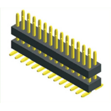
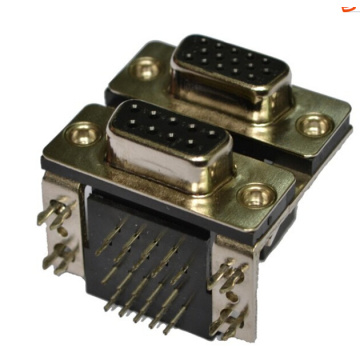
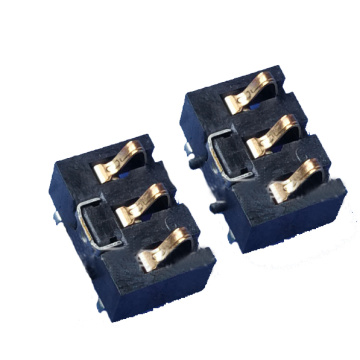
 Mr. Bob Yang